Russ White said:Hey guys, a quick update on the PCBs for the group buy. I have 2 PCBs left. If you want to get in on this first round of PCBs this is your last chance until I can get some more ordered and do a second round.
I am bit confused. This last PCB you did it yourself or had it made?
I ask this because if you are not DIYing these pcbs at home, it might be better putting some tracks on the component side. Dual-sided pcbs are difficult to DIY, and a strong reason to have them made.
Carlos
carlmart said:
I am bit confused. This last PCB you did it yourself or had it made?
I ask this because if you are not DIYing these pcbs at home, it might be better putting some tracks on the component side. Dual-sided pcbs are difficult to DIY, and a strong reason to have them made.
Carlos
Carlos,
I built my amp from a PCB I had made, and I am selling those as a group buy. No I am not selling PCBs from my layout. I will not do so until the prototype is thoroughly tested.
I am selling Mauro's "Revision A" layout which many have bought already.
As for my layout I see no compelling reason to do a double sided layout with Mauro's design. I want it to appeal to those who want to buy board, as well as those who want to etch it themselves.
Thanks Brian, Russ - I found a source for 2oz pcb that looks like a good price - $4.75 for 6X9" single sided 2oz. copper FR4. $3.10 for 1oz. They offer double sided as well. Here is a link... Don't know about the quality, I ordered a couple to check it out
http://northbaytechnical.com/materials1.htm
Stan
http://northbaytechnical.com/materials1.htm
Stan
sklimek said:Thanks Brian, Russ - I found a source for 2oz pcb that looks like a good price - $4.75 for 6X9" single sided 2oz. copper FR4. $3.10 for 1oz. They offer double sided as well. Here is a link... Don't know about the quality, I ordered a couple to check it out
http://northbaytechnical.com/materials1.htm
Stan
Ahh, you are talking about copper laminate. Thats not a bad price, but you can probably find cheaper...
Located them.
I looked at one of the local surplus stores and found some nice ones. They are Schrack brand, RTE24024, rated 10 amp ac, and 8 amps dc. They were not cheap, 3.95 each.
Got all my parts, time to finish matching them up, and start soldering. I use a LCR meter to match everything to 0.5% or better. The 0.1% listed for the 22K and 47K resistirs is tough, going to go with some old Holcos in the attic. My usual AB carbon comps drift too much for this level of matching.
One area of matching that is often missed is the zeners. They vary a lot. For this circuit, all four 12 volt should be matched up to 0.1 volts or so.
George
maf_au said:Hi.
Don't know about the generic name, but it's an Omron G2RL-24, Mouser Cat# 653-G2RL-24B-DC24. Bet there are equivalents, but I haven't found any locally yet.
Hopefully mine will turn up by the time I'm ready for it
Michael
I looked at one of the local surplus stores and found some nice ones. They are Schrack brand, RTE24024, rated 10 amp ac, and 8 amps dc. They were not cheap, 3.95 each.
Got all my parts, time to finish matching them up, and start soldering. I use a LCR meter to match everything to 0.5% or better. The 0.1% listed for the 22K and 47K resistirs is tough, going to go with some old Holcos in the attic. My usual AB carbon comps drift too much for this level of matching.
One area of matching that is often missed is the zeners. They vary a lot. For this circuit, all four 12 volt should be matched up to 0.1 volts or so.
George
Re: Located them.
Good quality relays are expensive. You should check that all contacts are silver or gold plated.
Carbon comps shouldn't be used in audio, even if some valve die-hards still say so. Drifting is certainly a problem when you need 0.1%. Best thing is to start with 1% metal-films and fine select them to 0.1%. What kind of wire terminals they have is also a question to look after, as newer Holcos now have steel terminals.
What I don't understand is what zeners are you talking about. If you mean to power the LM318s, what you need are good quality regulators, at least 7X12. I prefer LM3x7s, but the x12s should do if you use proper capacitors at the output. Using zeners to regulate would be a serious compromise, IMHO.
Carlos
Panelhead said:
I looked at one of the local surplus stores and found some nice ones. They are Schrack brand, RTE24024, rated 10 amp ac, and 8 amps dc. They were not cheap, 3.95 each.
Got all my parts, time to finish matching them up, and start soldering. I use a LCR meter to match everything to 0.5% or better. The 0.1% listed for the 22K and 47K resistirs is tough, going to go with some old Holcos in the attic. My usual AB carbon comps drift too much for this level of matching.
One area of matching that is often missed is the zeners. They vary a lot. For this circuit, all four 12 volt should be matched up to 0.1 volts or so.
Good quality relays are expensive. You should check that all contacts are silver or gold plated.
Carbon comps shouldn't be used in audio, even if some valve die-hards still say so. Drifting is certainly a problem when you need 0.1%. Best thing is to start with 1% metal-films and fine select them to 0.1%. What kind of wire terminals they have is also a question to look after, as newer Holcos now have steel terminals.
What I don't understand is what zeners are you talking about. If you mean to power the LM318s, what you need are good quality regulators, at least 7X12. I prefer LM3x7s, but the x12s should do if you use proper capacitors at the output. Using zeners to regulate would be a serious compromise, IMHO.
Carlos
Re: Re: Located them.
Carlos,
I agree with you about the resistors, but on the supply for the LM318 you are missing the point. He is building Mauro's circuit, which calls for the Zener, and it what the PCB he has is designed for, beside the rail voltage is close to the maximum for the regulators you mention.
I brought up the idea of using regulators and Mauro quickly reminded me of that fact.
Cheers!
Russ
carlmart said:
Good quality relays are expensive. You should check that all contacts are silver or gold plated.
Carbon comps shouldn't be used in audio, even if some valve die-hards still say so. Drifting is certainly a problem when you need 0.1%. Best thing is to start with 1% metal-films and fine select them to 0.1%. What kind of wire terminals they have is also a question to look after, as newer Holcos now have steel terminals.
What I don't understand is what zeners are you talking about. If you mean to power the LM318s, what you need are good quality regulators, at least 7X12. I prefer LM3x7s, but the x12s should do if you use proper capacitors at the output. Using zeners to regulate would be a serious compromise, IMHO.
Carlos
Carlos,
I agree with you about the resistors, but on the supply for the LM318 you are missing the point. He is building Mauro's circuit, which calls for the Zener, and it what the PCB he has is designed for, beside the rail voltage is close to the maximum for the regulators you mention.
I brought up the idea of using regulators and Mauro quickly reminded me of that fact.
Cheers!
Russ
Re: Re: Located them.
carlmart said:
Good quality relays are expensive. You should check that all contacts are silver or gold plated.
I can live with an eight amp rated relay. My power needs are usually mW levels. With the relay opening and closing on power up/down they should stay clean. These might be expensive relays, there were made in Austria.
Carbon comps shouldn't be used in audio, even if some valve die-hards still say so. Drifting is certainly a problem when you need 0.1%
I would never try for 0.1% match with carbon comp. These are only good for about 0.5% with carefull matching. I gave up on metal films along time ago. These Holcos are from the early 90's when they were wHOLe COpper. At least that is what Michael Percy said. They are listed as 0.25% already, getting to 0.1% should be easy.
I have all lot left from my tube amp building days. I do not want to discuss the AB's. Most who dis them have never used them. Or listened to good solid state gear using them.
What I don't understand is what zeners are you talking about. If you mean to power the LM318s, what you need are good quality regulators, at least 7X12. I prefer LM3x7s, but the x12s should do if you use proper capacitors at the output. Using zeners to regulate would be a serious compromise, IMHO.
You are right about using zeners as pull down voltage regulators. A three pin reg will measure much better. I am building the Rev C as designed. Here I suspect the absolute value of the zeners is not important, just that all four are very to the same voltage.
I may try a better reg later. A nice discrete wide bandwidth one would be great, but may be overkill in this application.
I have my own ideas about the parts used to build equipment, please overlook if not what is excepted.
George
Re: Re: Re: Located them.
Sorry, but that is a point I very, very strongly disagree with Mauro then.
Zeners are poor in every respect for supplies: noise, regulation, reliability, etc. Not even the worst regulator will be as bad as the best zener.
A good supply is essential to a small signal, and the better the supply the better your audio will be.
If the problem is the high rail voltage, then use a regulator that will take it or lower it with a transistor controlled by a zener. But using a zener direct in such a sophisticated circuit is a very poor solution, as I see it.
Carlos
Russ White said:
I agree with you about the resistors, but on the supply for the LM318 you are missing the point. He is building Mauro's circuit, which calls for the Zener, and it what the PCB he has is designed for, beside the rail voltage is close to the maximum for the regulators you mention.
I brought up the idea of using regulators and Mauro quickly reminded me of that fact.
Sorry, but that is a point I very, very strongly disagree with Mauro then.
Zeners are poor in every respect for supplies: noise, regulation, reliability, etc. Not even the worst regulator will be as bad as the best zener.
A good supply is essential to a small signal, and the better the supply the better your audio will be.
If the problem is the high rail voltage, then use a regulator that will take it or lower it with a transistor controlled by a zener. But using a zener direct in such a sophisticated circuit is a very poor solution, as I see it.
Carlos
Re: Re: Re: Re: Located them.
Carlos,
I very much respect your opinion, and I must ask you forgive my ignorance as I cannot argue the point.
I have my own ideas of course, but I also know one fact for sure. The Revision A amp Mauro has designed is simply stunning in sound quality and noise floor.
I see no fault in the zener approach, and Maruo indicated that calculations he used were based on the effects of the RCZ net on the opamps. So I would not be too quick to discount its worth.
In any case, the point is the same, it is what the schematic is designed for, and what the PCB he has implements, and it is very good.

Cheers!
Russ
carlmart said:
Sorry, but that is a point I very, very strongly disagree with Mauro then.
Zeners are poor in every respect for supplies: noise, regulation, reliability, etc. Not even the worst regulator will be as bad as the best zener.
A good supply is essential to a small signal, and the better the supply the better your audio will be.
If the problem is the high rail voltage, then use a regulator that will take it or lower it with a transistor controlled by a zener. But using a zener direct in such a sophisticated circuit is a very poor solution, as I see it.
/B]
Carlos,
I very much respect your opinion, and I must ask you forgive my ignorance as I cannot argue the point.
I have my own ideas of course, but I also know one fact for sure. The Revision A amp Mauro has designed is simply stunning in sound quality and noise floor.
I see no fault in the zener approach, and Maruo indicated that calculations he used were based on the effects of the RCZ net on the opamps. So I would not be too quick to discount its worth.
In any case, the point is the same, it is what the schematic is designed for, and what the PCB he has implements, and it is very good.
Cheers!
Russ
Re: Re: Re: Re: Re: Located them.
Then that is probably an area that may provide further improvements to the sound.
It should be interesting to try one of your assemblies with a regulator instead of the zener.
BTW: what's important on a regulator is the difference between input voltage and output voltage. In a 3X7 that difference is about 37v, and nothing will happen as long as you put a protection zener in the control leg and/or between input and output, which will protect the regulator and not be in the regulation path. 7X12 are the same.
In Mauro's amp he uses +/-12v for the LM318, and +/- 35v for the LM3886. The 23v difference would make the regulator dissipate about 100mW, which is close to nothing. The LM318 can also use +/- 15v supplies, but I don't think that might bring any benefits.
Carlos
Russ White said:
I have my own ideas of course, but I also know one fact for sure. The Revision A amp Mauro has designed is simply stunning in sound quality and noise floor.
I see no fault in the zener approach, and Maruo indicated that calculations he used were based on the effects of the RCZ net on the opamps. So I would not be too quick to discount its worth.
In any case, the point is the same, it is what the schematic is designed for, and what the PCB he has implements, and it is very good.
Then that is probably an area that may provide further improvements to the sound.
It should be interesting to try one of your assemblies with a regulator instead of the zener.
BTW: what's important on a regulator is the difference between input voltage and output voltage. In a 3X7 that difference is about 37v, and nothing will happen as long as you put a protection zener in the control leg and/or between input and output, which will protect the regulator and not be in the regulation path. 7X12 are the same.
In Mauro's amp he uses +/-12v for the LM318, and +/- 35v for the LM3886. The 23v difference would make the regulator dissipate about 100mW, which is close to nothing. The LM318 can also use +/- 15v supplies, but I don't think that might bring any benefits.
Carlos
Fine tuning
Well, maybe this project deserves being looked at from a different point of view.
Maybe there's a fine balance that Mauro got to by tuning different approaches.
And maybe this power method he used, even if not what we are used to, IS part of that balance.
As in my case I plan to try this project, I will provide space for both powering methods and see where it gets me.
Carlos
Hi Carlos,
I look for to explain in simple way my choices of PS.
But you recommends always to analyse in very detailed way this circuit, and to read all the comments of the thread , to understand the dynamicses of operation.
I usually build the circuits (by other ) in way extremely "believer" and eventually only "after" appraise the merits and the defects. Suggestion of don't "study ameliorations" before have a total follow-up of the circuit.
Sincerely is an little annoyed of has to it justify mine select, simply because as says Russ, if so sound much well ( and costs less ) because change?
However I answers you:
Ihave not data that a group (expensive and bulky ) formed by 7812+protections is more effective in this circuit. I am instead sure that a active component introduces problems to resolve.
If you observes well all the circuit is "different" from the commune think of the forums. For example the cap among v+ and v- on LM3886 and LM318 is a choice ignored by all in spite of is the only well-curb ( and demonstrable ) technique of follow-up of the PS troubles for a opamp ( would be enough know the structure of a opamp!).
Because 12V and not 15V ( or 18V )? LM318 is not a line preamp, but it is the heart of the circuit. The output voltage of LM318 is proportional to the load current. In conditions of clipping, all this systematizes becomes unstable, because the general gain margin is extremely high. LM318 stretch to compensate the LM3886 clipping going into clipping to his time. With 12V I limit the swing of exit to +-11V about, that correspond to about 11A, that corresponds to the internal limit of LM3886. If I increase the swing increase the instability to the clipping. The PS to zener, if LM318 has an anomalous absorption on account of oscillations or clipping, reduces the voltage ( on account of the upsurge of current on the res.) and it maintains the chip in safety zone.
This circuit has a few of "elementary" and all the components have a "conventional" and "non conventional" role. If I want take an oath GC I buy the kit from BrianGT !
Excuse me for the outlet, Carlos, not it's your fault, but have had to write much ( too ) times the reasons of my elementary technical choices .
I would be able challenges to the commentators: build an circuit with this compares quality/cost if succeed!
Notices technique: I would not go at once on the rev3 without try the revA or his variations...
Ciao
Mauro
mauropenasa said:Hi Carlos,
Notices technique: I would not go at once on the rev3 without try the revA or him/her/it his variations...
Ciao
Mauro
I would strongly agree here. I have now tried all three variations(by means of soldering accross pins and on the bottom of the board), and I find no fault in any of them, but I have settled on the Rev "A" design for my living room, as it suites my Cryolites perfectly.
Hi Russ,
This is an important news, that from value to my initial suggestions.
I am a lot of curious to know like configuration is preferred by the majority, because probably it is the more "balanced".
The comparison between the measures and the feelings of listening for me is important, because I am able elaborate some ( mine ) theories on the audio reproduction...
Ciao
Mauro
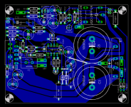
I think I almost have it ready to etch.
Ok, as some of you know I have been working on a monobloc "REV C" layout to prototype. Well I think I am close to having something to etch.
Could some of you please look it over to see if there any poblems. I am not interested in design/circuit changes, just problems with the layout.
Thanks!
Russ
Ok, as some of you know I have been working on a monobloc "REV C" layout to prototype. Well I think I am close to having something to etch.
Could some of you please look it over to see if there any poblems. I am not interested in design/circuit changes, just problems with the layout.
Thanks!
Russ
Attachments
- Home
- Amplifiers
- Chip Amps
- My "audiophile" LM3886 approach