I forgot me:
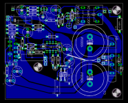
CONN3 = "output ready led " (Rdummy =R23) announce the normal conditions of operation.
CONN2= Power ON Led (external add Rdummy) or auxiliary (low load) fan.
The Voltage on CONN2 during the normal operation (relay ON) has to be among 16 to 24Vdc. If is to low means that the relay absorbs + current, and you be worthwhile decrease the R14 value in proportional way...
Ciao
Mauro
Mauro,
Thanks for the conn 2 & 3. It seems you thought of everything. I will make plans for "status" lights.
I see in another forum: http://www.diyaudio.com/forums/showthread.php?s=&threadid=60546
Graham and DestroyerX speak at length about twisted vs. non-twisted wire pairs. Can you tell us how sensitive this amp may be to this? I note your depiction shows the wires untwisted.
Thanks Mauro,
I called my friends at the University of Tennessee today, and I will be over there this afternoon for them to testthe amp, and check for oscillation (though I doubt it has any).
Thanks for all your help!
About the listening tests...
My listening room is about 15 x 28 and has sloped cielings starting at about 4'6" on the side going up to about 10ft.
The speakers I tested with are my tried and true Cryolites which are a two way design design by our own LouC. Excellent project for those into speaker building. I have 7 of these for my HT.
The source is a Denon 3910 slightly modded(not by me) with opa627s on output.
The preamp is my own freebird design (simple dual opa627 stereo preamp) with very close regulated PS.
Speaker cable is standard 12AWG copper.
Interconnects are my own stwisted pair solid core dual 18G copper terminated with gold plated RCAs. Pretty standard stuff. They have served me well for a while.
Cheers!
Russ
I called my friends at the University of Tennessee today
Wow, that honor, Russ. We hope that non-being too "severe".

Hi bg40403 , I have lost the thread of the conversation among Graham and Carlos. It seems me that they have spoken of "twist" in connection with the connection of BJT, and is not a problem that concerns this circuit. I suggestion to put the transformer on the side of the diodes and "twisted" the wires that go from the trafo to the card, and however reduce to the maximum this connection, because in those thread there are very strong interferences on account of the impulsive current of the diodes. Other connections are able behaviour as has done Russ...
Ciao
mauro
mauropenasa said:
I suggestion to put the transformer on the side of the diodes and "twisted" the wires that go from the trafo to the card, and however reduce to the maximum this connection, because in those thread there are very strong interferences on account of the impulsive current of the diodes. Other connections are able behaviour as has done Russ...
Ciao
mauro
Ahh.. let me see if I understand you Mauro.
You say the trafo could be one the rectifier side and not the heatsink side?
I can easily modify it to be that way, but then the signal wires get longer, and they run closer to the trafo, which I though was bad...

See I have a lot to learn I guess.
As it is there is no noise from my amp, no hiss, no humm at all. I tested it with the inputs shorted. It is the quietest amp I have, all the others have at least a tiny (though some barely perceptable) hiss when you put your ear to the tweeter, not this one.
Cheers!
Russ
As it is there is no noise from my amp, no hiss, no humm at all. I tested it with the inputs shorted. It is the quietest amp I have, all the others have at least a tiny (though some barely perceptable) hiss when you put your ear to the tweeter, not this one.
Hi Russ,
You are starting to understand the meaning of "virtual ground " and " good PCB layout ".
you are able weave the wire of the trafo and hold them far from the card. Or you turns the card with the headsink toward the connectors and passes with the cables over of it ( if you have space ).
When they connect an oscilloscope are able see if there are signals of trouble and when change if moves the trafo wires...
If its S/N satisfies you are able leave all as it is. ( remembered the Brian suggestion, you do some hole under and over the box for the heat...)
Ciao
Mauro
Re: Re: Re: I have my first "official" ref amp built.
What was not great quality? The pcb itself, which you got following your already explained procedures, or the pcb layout?
Who did this pcb?
Carlos
Russ White said:
the other one I built did not use all the smae values as Mauro did, and It was built on my own PCB (which was not great quality). This one is much better in every regard including sound.
What was not great quality? The pcb itself, which you got following your already explained procedures, or the pcb layout?
Who did this pcb?
Carlos
Re: Re: Re: Re: I have my first "official" ref amp built.
I have only been making my own PCBs for a little more than a month. The PCB I used for my first prototype was one of the first I ever etched, so there was some pitting and such. Plus at the time I only had 1oz copper laminate which is really insufficient for the task.
The board worked fine, the biggest problem was that I did not have the exact resistor values for the output resistor(I used .3R instead or .47R) which effected everything in the feedback loop...
The board was etched using Mauro's layout, not my own.
I will be etching some of my own monobloc "REV C" boards as soon as I feel confident the layout is good enough.
Any input in that regard is appreciated as I am itching to get that going.
Cheers!
Russ
Hi Carlos,carlmart said:
What was not great quality? The pcb itself, which you got following your already explained procedures, or the pcb layout?
Who did this pcb?
Carlos
I have only been making my own PCBs for a little more than a month.
The PCB I used for my first prototype was one of the first I ever etched, so there was some pitting and such. Plus at the time I only had 1oz copper laminate which is really insufficient for the task.The board worked fine, the biggest problem was that I did not have the exact resistor values for the output resistor(I used .3R instead or .47R) which effected everything in the feedback loop...
The board was etched using Mauro's layout, not my own.
I will be etching some of my own monobloc "REV C" boards as soon as I feel confident the layout is good enough.
Any input in that regard is appreciated as I am itching to get that going.
Cheers!
Russ
Re: Re: Re: Re: Re: I have my first "official" ref amp built.
Just to check we are talking of the same version: this is Mauro's Revision C, right?
About the pcb's copper: what was the problem with the laminate? What are you using now?
Only now did I check that the output resistor was a 7w type, and that you used a 5W wirewound type.
One suggestion I would have is trying to put two 3-watt 1-ohm metal oxide types there. They are non-inductive and usually better sounding.
But I think (please, Mauro, correct me if I am wrong) that that .33 resistor was not such a big problem for the feedback.
Good thinking for the center stand-off. I had not seen it on the previous layout. As the stereo board holds two middle-screws, it should be quite solid. But extra stand-offs on the "heatsink corners" might be good.
Carlos
Russ White said:I have only been making my own PCBs for a little more than a month.
The board worked fine, the biggest problem was that I did not have the exact resistor values for the output resistor(I used .3R instead or .47R) which effected everything in the feedback loop...
The board was etched using Mauro's layout, not my own.
I will be etching some of my own monobloc "REV C" boards as soon as I feel confident the layout is good enough.
Any input in that regard is appreciated as I am itching to get that going.
Just to check we are talking of the same version: this is Mauro's Revision C, right?
About the pcb's copper: what was the problem with the laminate? What are you using now?
Only now did I check that the output resistor was a 7w type, and that you used a 5W wirewound type.
One suggestion I would have is trying to put two 3-watt 1-ohm metal oxide types there. They are non-inductive and usually better sounding.
But I think (please, Mauro, correct me if I am wrong) that that .33 resistor was not such a big problem for the feedback.
Good thinking for the center stand-off. I had not seen it on the previous layout. As the stereo board holds two middle-screws, it should be quite solid. But extra stand-offs on the "heatsink corners" might be good.
Carlos
Re: Re: Re: Re: Re: Re: I have my first "official" ref amp built.
The problem with the 1oz laminate was simply that it was too thin(the copper).
Yes we are talking about Mauro's "Revision C" schematic. It is what I have designed this layout to implement.
Mauro has indicated(indeed it it is what is in my working amp) that 5W output resistor is adequate.
I am open to trying the 2 x 1R 3W metal oxide approach.
I would be inclined to say that the .33R resistors did indeed make an audible difference. My initial prototype (which is scrapped now) sounded overly bright and harsh. I am not absolutely sure if the output resistor was the only reason however.
Cheers!
Russ
carlmart said:
Just to check we are talking of the same version: this is Mauro's Revision C, right?
About the pcb's copper: what was the problem with the laminate? What are you using now?
Only now did I check that the output resistor was a 7w type, and that you used a 5W wirewound type.
One suggestion I would have is trying to put two 3-watt 1-ohm metal oxide types there. They are non-inductive and usually better sounding.
But I think (please, Mauro, correct me if I am wrong) that that .33 resistor was not such a big problem for the feedback.
Good thinking for the center stand-off. I had not seen it on the previous layout. As the stereo board holds two middle-screws, it should be quite solid. But extra stand-offs on the "heatsink corners" might be good.
Carlos
The problem with the 1oz laminate was simply that it was too thin(the copper).
Yes we are talking about Mauro's "Revision C" schematic. It is what I have designed this layout to implement.
Mauro has indicated(indeed it it is what is in my working amp) that 5W output resistor is adequate.
I am open to trying the 2 x 1R 3W metal oxide approach.
I would be inclined to say that the .33R resistors did indeed make an audible difference. My initial prototype (which is scrapped now) sounded overly bright and harsh. I am not absolutely sure if the output resistor was the only reason however.
Cheers!
Russ
Hi all,
The res. 5W "cement" wire have a low L, and bear peaks of current with about tens of Amp. The metal oxide res. are good quality but am not strong as the wire. I suggestion The 5W-7W "cement" wire.
The res. 0.33 creates a Zout of the current pump bridge of -20% in comparison with 0.47. Then it moves of 20% even the gain margin, the damping factor etc.... I prefer recommend the values that have given me good resulted on my bench...
Ciao
Mauro
mauropenasa said:
I prefer recommend the values that have given me good resulted on my bench...
Point taken.
Carlos
Russ White said:I forgot to answer the question about what copper laminate I use now. It is 1/16" FR4 with 2oz single sided copper. I also have some 2oz CEM of the same thickness.
Hi Russ, where do you purchase your "1/16" FR4 with 2oz single sided copper" board from? Is it pre-sensitived?
I'm another one of those flys buzzing around watching this thread loving the energy and devotion you guys are putting into it.
Stan
sklimek said:
Hi Russ, where do you purchase your "1/16" FR4 with 2oz single sided copper" board from? Is it pre-sensitived?
I'm another one of those flys buzzing around watching this thread loving the energy and devotion you guys are putting into it.
Stan
Stan I got that laminate at an estate sale a month or so back. I picked up something like 200 8x12 sheets. That should keep me busy for a while.
Its just plain copper, not the photo sensitive type. I use toner transfer method.Cheers!
Russ
- Home
- Amplifiers
- Chip Amps
- My "audiophile" LM3886 approach