hi linuxguru,
You need to download Eagle 3D.
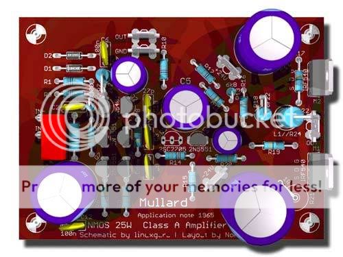
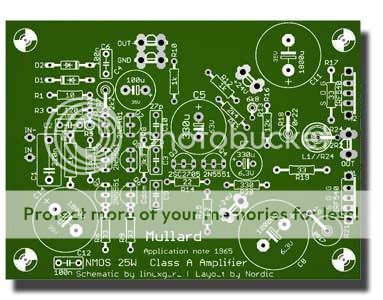
Although you can print directly from Eagle (the quality might be good enough) you can generate better quality prints by generating Gerber files and then printing them from a Gerber viewer. Gerber print on the left of image. See the tracks look real like on the produced PCB not what is on the screen.
Don't bother posting your Eagle files because the files can't be viewed or used by others. EDIT: Oh version 5 files.
regards
You need to download Eagle 3D.
Although you can print directly from Eagle (the quality might be good enough) you can generate better quality prints by generating Gerber files and then printing them from a Gerber viewer. Gerber print on the left of image. See the tracks look real like on the produced PCB not what is on the screen.
Don't bother posting your Eagle files because the files can't be viewed or used by others. EDIT: Oh version 5 files.
regards
Attachments

Hi, what an elegant layout....!!!!!!!!
To print PDF's, dowload DoPDF... it is a printer driver... instead of printing to paper, it prints to PDF.
Yes the 3D stuff is 50% done from within eagle... (google eagle3d)
and you also need Povray to render the files generated...
I was able to open his files but only with the trial version of eagle 5.
Greg: I'm using Eagle 4.16 for Linux - apart from the 100x80 mm limit of the trial version, is there any other limitation that prevents the files from being worked on by others? I was able to work on Nordic's original layout without any other problems. Even at worst, other users should be able to view the schematic and layout.
Hmm - I think I'll go the Gerber route, since I'm on Linux. I also like the curved/mitred edges on the tracks/pads in the Gerber image, rather than the angled/beveled edges in the screen view.
Nordic: Thanks, can you open my board and schematic files from the trial version of Eagle 4.16? I created it using the trial Linux version of Eagle 4.16, upgraded later to the registered version.
Hmm - it opens fine on another trial version of Eagle 4.16 for Linux here. Was the upload ok - I mean, did it unzip without errors?
If so, there's something broken in the file format between Eagle for Linux and Windows - I don't suppose it's a CR-LF issue.
Looks like the only way to read it then is to use the Eagle 5 trial version - too messy...
If so, there's something broken in the file format between Eagle for Linux and Windows - I don't suppose it's a CR-LF issue.
Looks like the only way to read it then is to use the Eagle 5 trial version - too messy...
linuxguru said:Hmm - it opens fine on another trial version of Eagle 4.16 for Linux here. Was the upload ok - I mean, did it unzip without errors?
If so, there's something broken in the file format between Eagle for Linux and Windows - I don't suppose it's a CR-LF issue.
Looks like the only way to read it then is to use the Eagle 5 trial version - too messy...
Unzip OK.
Exactly.
Nordic: I have modified your through-hole modern version, and fixed a few things and also made it more compact. The resistor on the solder side has been moved onto the component side. The Miller cap has been corrected. Two small film caps have been added to bypass the electrolytics on the rails. A couple of power resistors have been resized and moved. Lots of components and tracks have been shifted to either make it more compact, or to give additional spacing. Some track widths have been increased for better current handling, and some small signal track widths have been decreased slightly. Please check out the modified schematic and layout - I guess that it may open only with Eagle V5 trial, as before.
One useful thing that hasn't yet been added is to allow the use of either TO-220 or TO-247 power devices at the output - by using both component outlines, one above the other (this only works if both share the same G-D-S arrangement). Go ahead and do it if you're inclined, or I'll try to do it in the next iteration.
Everything else looks OK, but I haven't carefully examined all the small-signal pinouts. At this point, this board looks like the best layout of the lot.
Stee: That's neat - half-bridge, in other words. You need two caps instead of one, but the ripple current requirement of each cap gets halved, because there are now two charge/discharge paths.
Attachments
I like what you did...
I modified a few thin traces, and also lined up the small components a little better...
I think those 100n caps are best applied to the bottom of te board straight to the pins of the caps they are bypassing.
I'd preffer to move the two large caps by the outputs to the side to make it easier to access the transistor screws...
Attachments
OK, then with your agreement, I moved the caps to the side again...
Also put the small parts on the input on a slightly larger (2.5mm) grid... things look easy on the screen, until you have to solder diy boards without solder mask... so a bit of space between the solder pads are good... I think the board actualy shrunk by a milimeter or two again..
Also put the small parts on the input on a slightly larger (2.5mm) grid... things look easy on the screen, until you have to solder diy boards without solder mask... so a bit of space between the solder pads are good... I think the board actualy shrunk by a milimeter or two again..
Attachments
I have a question to help me complete my prototypes.
Re:http://www.diyaudio.com/forums/attachment.php?s=&postid=1526992&stamp=1212390542
What is the value of the inductor on the output?
Also what are we looking at in terms of a PSU for these...?
I am going to try it with a regulated supply first as I only have a collection of transformers giving about 35VDC on hand.
It's 2 uH - looks like the 'u' symbol didn't get printed out on the LTSpice schematic - that's another LTSpice on Wine/Linux gotcha.
You can approximately calculate the number of turns for an air core inductor using this formula:
L = r^2 * n^2 / (3.5 r + 4 len)
where:
L in the inductance in uH
r is the radius of the former in cm
len is the length of the former in cm.
n is the number of turns.
The value is not critical - 8 turns on a 8 mm diameter (4 mm radius), 1 cm long cardboard former gives about 1.9 uH. Alternatively, if the wire is stiff enough, you can wind it on a 8 mm diameter capacitor or dowel, slip it out and put a few drops of super glue on the windings to hold its shape.
If the damping 2.2 ohm resistor is non-magnetic, you can measure its average diameter (should be 5 to 8 mm for a 2W resistor) and wind the inductor around it - it may require a few more turns to compensate for the smaller diameter. You can use a single strand of CAT5e cable (with insulator) to wind the inductor around the resistor. The value of the resistor is also not critical - 2 to 10 ohms should work. I need to check the simulation numbers for THD20 with a 10 ohm resistor, but it's not likely to differ by more than a few dB - it's outside the NFB loop.
Thanks man, I thought 2H on the output could not be right, glad to see it is only 2uH... ( I generaly run my amps without output inductors, but I will humor you and try it again.
I have a nice DIY Inductance meter with LCD display... realy easy to make nice matched L's useing it...
I have a nice DIY Inductance meter with LCD display... realy easy to make nice matched L's useing it...
I haven't yet simulated the PSRR on this circuit, so I'm not sure yet about the extent of 50 Hz feedthrough - I suppose it will be OK with an unregulated supply. You can try it out with +/- 18v initially, and then go to +/- 24v if the heat looks manageable.
You can skip the output inductor for initial testing if your load is fairly clean - i.e. mostly resistive with minimal shunt capacitance. If it is unstable without the inductor, you can add it - its function is mainly to maintain isolation of the NFB loop from difficult reactive loads like electrostatic speakers.
BTW - I forgot if there's a Zobel/Boucherot cell in your layout. If you've skipped it, it's probably useful to add it if there's enough space on the board for it - again, it's mainly for stability into difficult loads.
Thanks for the TO-247 outline - I've located inexpensive IR IRFP150 devices here; IRFP240 is nearly twice as expensive. If it turns out to be sonically ok both in the sims and the prototype, that's the NMOS Hexfet that I'd recommend. Stability still needs to be checked, since Cgs is likely to be large...
- Status
- This old topic is closed. If you want to reopen this topic, contact a moderator using the "Report Post" button.
- Home
- Amplifiers
- Solid State
- Mullard SS power amplifier