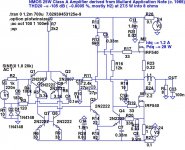
Hi Linuxguru & John, Here's the circuit, Single ended input stage with a D.C. servo (specified Op Amp needs only -12v rail). Quiescent current 80 to 100 ma. A 0.22 ohm output resistor is fitted. I may go on to develop this further, in particular the use of separate rails for the front end and drivers. PSU rejection is a weak point although it certainly does not detract from the listening experience. As I say, it genuinely has that magical quality, where the true character and timbre of instruments comes across. The soundstage is wide and deep, instuments can be correctly placed. This is not just with an odd "demonstration quality" recording, the musical worth of the majority of discs comes across. I have for comparison one of Doug Self's designs built to Dougs design on the official PCB 's and musically speaking this is just 2 dimensional, and flat sounding. I have been able to compare directly with the new Sugden A21SE. ") Smiles all the way. This design draws on some of the work and ideas of the late John Linsley Hood. I appreciate any thoughts, thanks
Smiles all the way. This design draws on some of the work and ideas of the late John Linsley Hood. I appreciate any thoughts, thanks
Regards Karl
Smiles all the way. This design draws on some of the work and ideas of the late John Linsley Hood. I appreciate any thoughts, thanksRegards Karl
Attachments
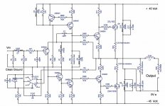
Just a quick question on inspection of the schematic - what's the quiescent current in the output devices? I assume it's biased to Class-A - the quiescent current can't be determined without knowing the value of R8 and the MOSFET curves.
Observation/suggestions:
1) Why not use a low-impedance Vbe-multiplier instead of R8?
2) How about using a Self Type-II drive, by disconnecting the junction of R19 and R20 from the output node (i.e. at the Zobel) and floating it?
3) It might be worth replacing C7 with a second-order lead compensation network consisting of a 47pF-470R-47pF (values are approximate) grounded T-network.
It runs at around 80ma quiescent, just below the change from neg to pos tempco in the FET's. I found no audible benefit going higher (Speakers used B&W 703's with 3 ohm impedance minima). R 8 determined on test ( don't like pots if it can be avoided ). R19/20 , yes that could be an advantage, pull the charge from the gates better. I will look into that. The compensation network on the VAS, I just kept it simple, but might be worth trying along your lines of thought.
Have you any thoughts on the unequal gate capacitance of complementary FET's. Some designs add a cap to equalise the imbalance, I have often wondered though about making the gate stopper resistors unequal instead.
Thanks very much for your comments and suggestions, the only problem I have is that it performs so well the motivation for another design and build isn't quite there yet. I also want to get into PIC programming, I had to buy in a module to implement the remote control functions on this amp.
Karl
Interesting - the 1972 version has a Zobel and several speed-up capacitors, but the only compensation seems to be the C5-R6 (lag) network. As previously noted on this thread, the pre-driver bootstrap C8 seems to be on the 'wrong' side - driving the lower output.
Input stage bootstrap C4-R3-R4 should help increase the input impedance significantly - I need to simulate this to see if the sonics remain unaffected, but it looks like a zero-cost improvement that allows the use of a much smaller input coupling capacitor, which could be a high-quality polystyrene or similar.
Input stage bootstrap C4-R3-R4 should help increase the input impedance significantly - I need to simulate this to see if the sonics remain unaffected, but it looks like a zero-cost improvement that allows the use of a much smaller input coupling capacitor, which could be a high-quality polystyrene or similar.
Hi, Linuxguru,
Interesting development Since you have put differential input (Q1-Q2), this amp can be DC coupled with +/-rails, eliminating C9, R1-R2-R3-C2 (and put another R to ground for DC reference). What do you think?
Hi, AKSA,
If Linuxguru has change the singleton input stage to differential input stage, would the sound/sonics signature of singleton input stage disappear?
Interesting development
Since you have put differential input (Q1-Q2), this amp can be DC coupled with +/-rails, eliminating C9, R1-R2-R3-C2 (and put another R to ground for DC reference). What do you think?Hi, AKSA,
If Linuxguru has change the singleton input stage to differential input stage, would the sound/sonics signature of singleton input stage disappear?
Lumanauw: Yes, it's easy to modify for split rails (say +/- 18V), allowing the removal of the output DC blocking capacitor as well as permitting a very high impedance input bootstrap.
Meanwhile, here is a further set of tweaks to permit the use of a smaller input coupling capacitor. As shown, a 10 nF capacitor gives a lower corner frequency of ~18 Hz, which may be a bit high for some tastes (22nF/8Hz may be more acceptable). The advantage is that 10 nF is available in polystyrene. The sonics are more or less the same as the previous version; slight changes to the compensation schema now allow the use of 2R loads in Class AB without loss of stability (albeit with significantly higher distortion).
Meanwhile, here is a further set of tweaks to permit the use of a smaller input coupling capacitor. As shown, a 10 nF capacitor gives a lower corner frequency of ~18 Hz, which may be a bit high for some tastes (22nF/8Hz may be more acceptable). The advantage is that 10 nF is available in polystyrene. The sonics are more or less the same as the previous version; slight changes to the compensation schema now allow the use of 2R loads in Class AB without loss of stability (albeit with significantly higher distortion).
Attachments
I believe the sonics of an amp are hugely related to how the amp behaves when driving speakers "proper". Forgetting for a minute the fact that it is a reactive load, it is also a pretty good voltage source (microphone). Each channel in a stereo pair must be feeding back a distorted version of the audio back into the NFB node. The "singleton" input stage I have always found more docile to work with, I am not using this an excuse for poor layout etc, it just seems an inescapeable fact. There our designs out there that are technically beyond reproach, sonically they fail at the first hurdle. Why ? Have you ever "flicked" a bass unit with your finger while connected to an amp and looked at the NFB signal.
Linuxguru, may I ask, do you find simulation correlates with the "listening experience" ?
Linuxguru, may I ask, do you find simulation correlates with the "listening experience" ?
Good points - I use simulation as the starting point to get to something useful that can be elaborated/tweaked by actual listening later. If something looks harmonically bad or unstable in simulation, usually no amount of tweaking can save it in a real implementation. In that respect, simulation is useful to weed out bad ideas.
It's also useful for sieving out good ideas that may have been missed earlier due to a sub-optimal or incomplete design elaboration - the Mullard falls in this category. I can see why it did not become more popular, although it deserves to be.
It's also useful for sieving out good ideas that may have been missed earlier due to a sub-optimal or incomplete design elaboration - the Mullard falls in this category. I can see why it did not become more popular, although it deserves to be.
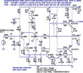
Here's a further set of modifications - it's now a dual-rail topology, with input bootstrap to lower the value of the input coupling cap. The output coupling capacitor is gone. The output devices are commodity, industrial-grade $0.50 TIP142 darlingtons. The compensation has been tweaked to maintain stability into loads as low as 2R, as well as reactive loads of up to 4 uF in parallel with the load, while still managing acceptable distortion. Sonics have been improved into normal loads, with dominant even-harmonics into resistive loads in both Class A and AB.
Edit: The current mirror on the input LTP may be controversial, but the simulation reveals that the sonics are not impaired - the gains outweigh the disadvantages. However, the 2-transistor CCS has been removed and a resistive modulated current source is used in its place - it seems to be very beneficial to the sonics.
Edit: The current mirror on the input LTP may be controversial, but the simulation reveals that the sonics are not impaired - the gains outweigh the disadvantages. However, the 2-transistor CCS has been removed and a resistive modulated current source is used in its place - it seems to be very beneficial to the sonics.
Attachments
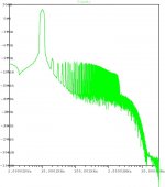
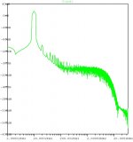
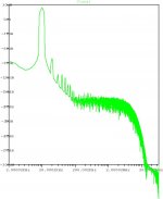
This is the closed-loop frequency response, 1 Hz to 100 MHz, with a load of 4R || 0.1 uF. The lower corner frequency is at ~10 Hz, and the upper corner frequencies are at ~500 kHz, followed by a gentle rolloff to ~3 MHz, after which it falls off the cliff.
I might tweak the compensation later to reduce the upper cutoff, but it's good enough as it is:
I might tweak the compensation later to reduce the upper cutoff, but it's good enough as it is:
Attachments
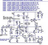
Here's the NMOS FET output version - it's topologically similar to the darlington version, but with higher rails (+/- 24v) and minor tweaks for stability, biasing, improved rail swings, etc. A wide variety of MOSFETs are usable, including garden-variety IRF540 (shown). There's a minor error in the schematic shown - Q3 isn't a 2N2222, but almost anything with a Vceo > 50 V (bc560/2sc2705/bf422/bf469 will do fine).
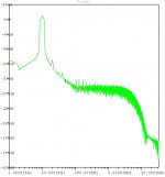
It simulates with ~ -105 dB THD20 at +/- 21 V output swings into 8R || 100 nF (~27.5 W), with H2 dominating.
It simulates with ~ -105 dB THD20 at +/- 21 V output swings into 8R || 100 nF (~27.5 W), with H2 dominating.
Attachments
Addendum to schematic above: To allow a wider variety of NMOS Hexfets (with large variations in Cgs) to be usable without tweaks, add a Miller capacitor of 10 to 47 pF between B-C of VAS BJT (Q3). This provides extra phase-margin at the expense of increasing distortion, particularly H3, by 5-10 dB.
I'll post an updated schematic later, with the modified compensation schema in conjunction with IRFP140 output devices; sonics are generally similar with H2 dominating in either case.
I'll post an updated schematic later, with the modified compensation schema in conjunction with IRFP140 output devices; sonics are generally similar with H2 dominating in either case.
- Status
- This old topic is closed. If you want to reopen this topic, contact a moderator using the "Report Post" button.
- Home
- Amplifiers
- Solid State
- Mullard SS power amplifier