Well, after a good read through that site, it seems I'll have quite good distortion figures for this amp, maybe even exceptional!
I've made some of my own changes according to Self's instruction.
He mentioned that A1302/C3281 have respectably low LSN,
which seems to be quite a coincidence since they are the exact OT's I'm using here!
I've made some of my own changes according to Self's instruction.
He mentioned that A1302/C3281 have respectably low LSN,
which seems to be quite a coincidence since they are the exact OT's I'm using here!
hmm..
I've been following this thread for a while. Since I'm about to build a modified Rod Elliot amp too.
Here's my version of the circuit.
What do you think about this?
I'm a little unsure about the value of the degeneration resistors, I do understand that these will reduce open-loop gain much though.
I've been following this thread for a while. Since I'm about to build a modified Rod Elliot amp too.
Here's my version of the circuit.
What do you think about this?
I'm a little unsure about the value of the degeneration resistors, I do understand that these will reduce open-loop gain much though.
Attachments
Well, 500VA is a little skimpy, so distortion figures and power linearity may suffer lightly, but no too much...
For my amp, I'm using a 5000VA transformer, but it was just a fluke that I happened to have it around as I would never be able to afford a transformer that enormous! I came out of a fiching
boat and was used as an isolation transformer for everything...
It gives me 55-0-55 out so I'll have a higher voltage than listed in my diagram.
Also, what program did you use to make that diagram? It looks like the same as ESP and I like it better than my prog...
EDIT ops, I failed to read one of your messages pertaining to the latter question, so don't bother to answer again
For my amp, I'm using a 5000VA transformer, but it was just a fluke that I happened to have it around as I would never be able to afford a transformer that enormous! I came out of a fiching
boat and was used as an isolation transformer for everything...
It gives me 55-0-55 out so I'll have a higher voltage than listed in my diagram.
Also, what program did you use to make that diagram? It looks like the same as ESP and I like it better than my prog...
EDIT
ops, I failed to read one of your messages pertaining to the latter question, so don't bother to answer againWell, all I'm saying is that he only has 200W headroom before the transformer begins to collapse. Which is good, but I like conditions where there is no possibility of voltage drop from the PSU at all. But my preferances are somewhat tainted I agree. I seem to have some ability to obtain components like that transformer on a daily basis. But I'm running out of room for soo much junk so I decided to start making good things like amplifiers out of it...
EDIT: Also, 60000uF caps will really help the demand for current transients anyway...
EDIT: Also, 60000uF caps will really help the demand for current transients anyway...
Well, that's the thing. My system will be using two class AB's maybe going to 400watts each and some auxillary stuff all off that transformer. So, I do still have excess current availability, but that means plenty of headroom and thus all the power leftover needed for rel big transient thumps. I mean, my speakers are really huge too, and it takes crazy levels of current to control them. So it works out fine.
I guess it really depends on equipment and preferences though as well. Some speakers are more efficient and thus require less power, or are simply smaller and may be ported so they'll draw less current..
Think two 12" woofers in a sealed enclosure and a high power onkyo mid and medium horn tweeter. These cabinets have about 100 litres of volume and require LOTS of current for that window break type of thump I like. But again, not many speakers are as inefficient as mine too.
aww it still makes a difference to some extent
Anyway, if I need more power, I can make my amp bigger, and I don't have to worry about changing the power supply with it.
And anyhow, If it starts to clip, I can stop turning up the volume.
I don't think I'll need to run it at that level too much anyway, I'll blow my eardrums if I'm in the room.
Anyway, if I need more power, I can make my amp bigger, and I don't have to worry about changing the power supply with it.
And anyhow, If it starts to clip, I can stop turning up the volume.
I don't think I'll need to run it at that level too much anyway, I'll blow my eardrums if I'm in the room.
Duo said:aww it still makes a difference to some extent
Anyway, if I need more power, I can make my amp bigger, and I don't have to worry about changing the power supply with it.
I'm not quite sure how you intend 'make my amp bigger' without changing the supply as it is the supply that dictates the maximum voltage swing of the amp. Of course, you could always lower the closed loop gain and then bridge it increasing gain until you have the desired maximum output power indeed this is a very real option with such a HUGE power supply but it is not without it's own complications (you'd need to add more output devices, build another 2 channels and probably add a delay circuit to save yourself/your house/your equipment/your neighbours from the turn on thump).
But as you stated, I cannot imagine your need for more than 350-400W.
Big caps really help with the bass thumps
Yes, I did mention caps elswhere, and they do make a good difference. Also, if I really wanted to go nuts, I could instead plug my power supply in to 220 and upgrade my amps for 110-0-110
operation, however, a 220 volt power supply rail is bloody insane.
I might as well have a tube amp at that voltage
But I must agree with the fact that 350-400 watts should be plenty.That's that much for each speaker and the double for the fact that there are two of them for the whole room.
operation, however, a 220 volt power supply rail is bloody insane.
I might as well have a tube amp at that voltage
But I must agree with the fact that 350-400 watts should be plenty.That's that much for each speaker and the double for the fact that there are two of them for the whole room.
recommend also that you put a res between the emitter and -60 V. This creates a local feedback and you will get a more temperature stable stage and lower distortion. You will also improve the phase margin (less possibilities to oscillation) and get a more predicable gain. Voltage across this res should be at least 0,5-1 V. The same goes for Q1 and Q2. 47-220 ohms are normal values. You won't improve thermal stability (not a problem here) but you lower the dist. You will also get slightly higher noise but that's not a big problem, usually only critical in mic and phono amps.
Why should the voltage across the resistance be atleast 0,5-1V?
And aprox. how much open-loop gain is recommended?
/Freddie
letting the emitter resistor have 0.5 - 1 volt accross it improves the VAS circuit by improving linearity and compensates for any current changes accross the collector by feeding a negative signal back to the base. Thus introducing local negative feed back and also making the stage more temperature stable. The reason the voltage is 0.5-1 is so you have a good amount of feedback, since more voltage accross will mean more feedback and less voltage means less feedback. 1 volt seems to be good since it doesn't cause too much of a voltage drop, and it permits a useful amount of feedback for the gain of the transistor and the current flowing through it... The reason your gain is more predictable is because you can calculate for the feedback of the more stabilized transistor and achieve a less variable number...
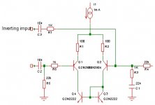
And, I know i could bridge two amps and go BAL to the speaker, but I don't have enough parts for to amps. I did hear that you can feed the inverted side of the BAL input to th other side of the LTP but I'm not sure what to do to make it work. I'd imagine that feeding the signal right to the base of the transistor would work through a 1 or 2k resistor as with the other side and let the feedback also go in there, but I'm not COMPLETELY sure of this.
Here's an example of what I'm thinking so you get an idea....
EDIT:nevermind R6 and R5, they are completely wrong values
Here's an example of what I'm thinking so you get an idea....
EDIT:nevermind R6 and R5, they are completely wrong values
Attachments
- Status
- This old topic is closed. If you want to reopen this topic, contact a moderator using the "Report Post" button.
- Home
- Amplifiers
- Solid State
- much less crazy idea