Yeah, I think the data sheets I've been looking at are quite bad...
I really like the ones at onsemi, curves and everything!
Well, now that I knw I had the wrong transistors in there, I'll go an pick some better ones,, Do you have any suggestions on transistors I could pick for the drivers and diff stage and diff stage current sink?
I really like the ones at onsemi, curves and everything!
Well, now that I knw I had the wrong transistors in there, I'll go an pick some better ones,, Do you have any suggestions on transistors I could pick for the drivers and diff stage and diff stage current sink?
actually, I think I'll use MJE340/350 rated at 300Vceo and 1 amp, more than enough to handle all kinds of OT pairs and lot's of room with the 120v pwr supply! Trouble is, I'll still have to find some small pnp's rated at maybe 80 volts but I need about an hfe of 100 for them too
EDIT: Dang just look em up again, only.5 amps, I need to idle
the OT's a .1 amps, which means, .2 amps collector current for the MJE340/350 which will only take .5, no real safe operating range there...
Trouble is, I'll still have to find some small pnp's rated at maybe 80 volts but I need about an hfe of 100 for them too EDIT: Dang just look em up again, only.5 amps, I need to idle
the OT's a .1 amps, which means, .2 amps collector current for the MJE340/350 which will only take .5, no real safe operating range there...
With R2 at 100 ohms, you will want VR2 at abour 220 ohms,
not a 10K pot. I suggest a 500 ohm pot with the wiper
attached to the + side so that the amp doesn't suffer
catastrophic failure when the wiper gets flakey.
Same with the bias pot. Use a fixed resistor from C to B
and a 5K pot from B to E.
Get rid of d3 and d4 and use some flyback diodes on the
output stage.
Mr. Pass,
Thanks, it was by accident that I wrote a 10k pot on the end of the diff amp, I meant 1k, but If you say 500ohms is good, i certainly believe you... By the way, what do you mean by flyback
diodes, I've never heard of them before... Also, I figured out that if I expect 400 watts out of this thing, I'll have to put double the transistors in the OT stage to comensate for temp derating and kick back current from the speaker... I suppose you might have meant flyback diodes as in a way of preventing speaker back-current??? Please tell me more... I'll go and update the schematic with your ideas right now...
Duo said:By the way, what do you mean by flyback
diodes, I've never heard of them before... I suppose you might have meant flyback diodes as in a way of preventing speaker back-current??? Please tell me more...
Think the following:
8 V DC out to the speaker, shut off the current.
What happens? The speaker has 8 ohms resistance, just for calculation
1 A flows despite the fact that the transistors are shut off. You can't turn off current in notime. Compare, you can't charge a capacitor in notime.
Where goes the current?
I can tell you that, through the transistors and they can (or will) brake. If you have diodes across collector-emitter current can go through them for a while. MOSFET's have diodes by nature but they have a little bit higher losses then regular ones but in audio amps it's no big deal.
As others have pointed out BD139 has too low voltage rating. You must have 200 volts at least. I recommend also that you put a res between the emitter and -60 V. This creates a local feedback and you will get a more temperature stable stage and lower distortion. You will also improve the phase margin (less possibilities to oscillation) and get a more predicable gain. Voltage across this res should be at least 0,5-1 V. The same goes for Q1 and Q2. 47-220 ohms are normal values. You won't improve thermal stability (not a problem here) but you lower the dist. You will also get slightly higher noise but that's not a big problem, usually only critical in mic and phono amps.
If I were you (which I'm not ), I would make a few very small changes to the original circuit. I would add a current mirror and degeneration resistors in the diff stage, and I would add a multislope protection circuit in the OPS. Bridging is a great idea to reduce stress on the devices.
Flyback diodes are reverse biased from each sypply rail to the speaker output.
), I would make a few very small changes to the original circuit. I would add a current mirror and degeneration resistors in the diff stage, and I would add a multislope protection circuit in the OPS. Bridging is a great idea to reduce stress on the devices. Flyback diodes are reverse biased from each sypply rail to the speaker output.
Well, I could build a bridged amp... But I thought of something, why don't I just run it with+/- 45volts, then I'd have a much easier time with things, nicer on the OT sets and I can use more generic transistors in the drivers and input... Then It'll only OT about 250 watts, but that is still enough for now.
peranders said:
Think the following:
8 V DC out to the speaker, shut off the current.
What happens? <snip>
(the existing current continues flowing) <- edited by Circlotron ) despite the fact that the transistors are shut off. You can't turn off current in notime. Compare, you can't charge a capacitor in notime.
Where goes the current?
I can tell you that, through the transistors and they can (or will) brake. If you have diodes across collector-emitter current can go through them for a while. MOSFET's have diodes by nature but they have a little bit higher losses then regular ones but in audio amps it's no big deal.
That is to say, if you shut off the bottom transistor suddenly when it is supplying current to an inductive load e.g. speaker the voltage on the output rail will "fly back" toward the upper supply rail and even go way past it if nothing is there to stop it. A normally reversed biased diode across the upper transistor C/E will stop the voltage going more than one diode drop above the upper supply rail. Incidentally in doing this it returns any excess reactive power back to the supply rails - a big deal with class D and also AC motor drives. Not a bad idea to put a reversed diode from anode to earth in a tube amp too; makes the socket less likely to flash over if you forget to connect the speaker.
I think the term "flyback" comes from the scanning cct of tv's, monitors etc where the beam scans across as the current through the deflection yoke inductance rises, and when the current is suddenly shut off the electron beam "flies back" while the flyback diode gives this interrupted current somewhere alternate to go.
GP.
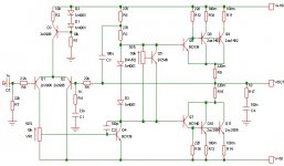
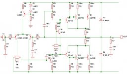
Well, i dumped a bunch of opinions into my schematic... i think I'll just run it a lower voltage and get less power... I really don't "need" over 200 watts, so making this thing do 250 with the parts I'vre already designed it for should be quite easy...
Revisions: Added flyback diodes
Changed some pot configs
Removed the old bias diodes
Stuck a balance resistr into the diff pair
A few other tiddly not to be bothered with
Revisions: Added flyback diodes
Changed some pot configs
Removed the old bias diodes
Stuck a balance resistr into the diff pair
A few other tiddly not to be bothered with
Attachments
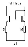
You need no balance pot if you use a current mirror. It will balance the legs almost perfectly, and improve PSRR, linearity, and slew rate. All you have to do is stick something like this between your diff legs and the rail. The resistors are chosen to drop 50mV. 0.05 / 0.00335(current through each leg) = 14.925.
P.S. I had those transistors upside-down for a moment, it's corrected now.
P.P.S. No, they were right the first time, the're right now, my appologies.
P.S. I had those transistors upside-down for a moment, it's corrected now.
P.P.S. No, they were right the first time, the're right now, my appologies.
Attachments
You have interchanged emitter and collector. Emitter towards the res. OK, you have changed this meenwhile I wrote this....
Recommendation from me: Never use only 2 pins from a pot. Use all the three ones even if you only want a variable res. If the potentiometer gets "raspig" you still have some function. It's not very important in your application though but it's a good rule.
Recommendation from me: Never use only 2 pins from a pot. Use all the three ones even if you only want a variable res. If the potentiometer gets "raspig" you still have some function. It's not very important in your application though but it's a good rule.
Duo said:Does anyone know of a good site with lots of transistor specs and curves? Also, as most of you have seen, I have transistors of insufficient Vceo for this amp, can anybody suggest anything that'll work in here?
Try http://www.questlink.com for starters.
- Status
- This old topic is closed. If you want to reopen this topic, contact a moderator using the "Report Post" button.
- Home
- Amplifiers
- Solid State
- much less crazy idea