Maybe I hear some sarcasm in there? But I cleared (by the people of ATL) to help you identify the current 'best' circuit, it’s the attached one (circuit M in the file).
Hi Frans,
What is the purpose of IM resistor? Is it some simulation(parasitic) value to be neglected in real build?
Hi Frans,
What is the purpose of IM resistor? Is it some simulation(parasitic) value to be neglected in real build?
Just an easy place to measure cuttent (I used a 1 pico Ohm resistor)
A 1 pico Ohm resistor is innovative so Rams would aprove on that.
Ricardo, without those caps the circuit would have no bass.
Why that is : It forms a high pass filter with the forward impedance of the input stage
( sans the mirror that is ) and that is very low because we want low noise into low impedances. How the circuit works in detail ?
Apply for a PHD degree at Gerhard University.
A 1 pico Ohm resistor is innovative so Rams would aprove on that.
Ricardo, without those caps the circuit would have no bass.
Why that is : It forms a high pass filter with the forward impedance of the input stage
( sans the mirror that is ) and that is very low because we want low noise into low impedances. How the circuit works in detail ?
Apply for a PHD degree at Gerhard University.
So those caps are responsible by the circuit bass response.... These are very important units.
Bass depends on those caps.... Now I am wondering about cap quality
")
I am working with available parts in my sock (4700u, 3300u and 2200u Pana FC).
As for the Gerhard PHD.... I want to but I must have to learn a lot before that... I am glad you are not like some that only share ideas with other PHD´s.
The issue is the cap size... only small caps will fit. I will experiment with what I have got and will tune after with bigger capacity caps.
Last edited:
Just an easy place to measure cuttent (I used a 1 pico Ohm resistor)
Thanks Frans!
Hesener, C5 should be 1uF printed on the PCB and not 100nF i think, i also can not find the 1MOhm resistor from output to servo.
noted, thanks
the 1M is upper righthand corner, between bc337 and 6.8nf caps
What is the big, single 15kOhm resistor in the middle of the PCB, left of the RIAA ?
thats R19, where michael said to let space for a bigger resistor due to higher power dissipation

Why ?
Most probably for thermal constraint, automotive design normally would be for -50C to +100C many (many many ...) cycles. Internal bounds, lead bounds and material tolerance could be at risk.
(that is where I come from
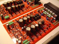
)stuffing is finished ;-)
boards are full - power up planned for monday ;-)
this is with LCR caps, Dale resistors, and as good a matching as I could get. Input transistors are matched to 0.7% between all of them, the rest less... Its probably required to order 200...300pcs of each transistor type to get a perfect matching.....
Attachments
Well well, we can shake hands than buddy
Likewise here
Audiofanatic
Cool, and I can be a bit more specific on that. Once (a long time ago) I worked for Motorola, HP and International Rectifier (among others) as an industrial 'components in-design specialist', working with our customers helping with their designs (at the customer’s site) mostly do select components to fit them to their specific environment. I have done planes, trains and automobiles (among others, including the particle accelerator in Cern
).