Hi Frans,
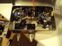
just found an appropriate case for my Paradise - ATL modded. Hope the ATL approves the looks! ;-)
Way cool
 the man at the ATL have taken the day off for beer and women just to celebrate the discovered housing, they love it too
 'Area 51' the amazing numbers
Just before the man at the ‘Alien Technology Laboratory’ went off for a free day (they really like that enclosure) they came up with some practical (it’s just a word they [people I know at ATL (always dressed in black)] say
 ) numbers for the ‘Area 51’ circuit (it seems that they (the ATL man) also read this forum and found the Bksabath posted message).
Any way here is there text:
======================================================
This ATL technology is freely available to anyone mad (or brave) enough to try it, use the attached files with care. When using any of these ATL findings please add an acknowledgement to ‘Area 51’-component and ATL to your project.
No further work/development will be done (on this subject) by the ATL department.
=-=-=-=-=-=-=-=-=-=-=-=-=-=-=-=-=-=-=-=-=-=-=-=-=-=-=-=-=-=-=-=-=-=
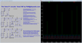
Vout = 30V (as needed for the Paradise phone amp, with an bit of margin)
Iout = 150mA (one (mono) amp (left or right))
Rser(transformer) = 4 (taken from an actual 25V 15VA toroidal transformer)
Vripple = 5% = 1.5V (this determines the buffer capacitor size)
'Standard' circuit (A)
---------------------------------------------------------------------------------------------------------------------------
Transformer voltage = 34.5V / sqrt(2) = 25V (this is with some margin)
Capacitor size(min) = 760uF (for 5% ripple, any larger value is allowed)
Capacitor voltage specification = 34.5V * 2(spike margin) = 70V(63V is ok)
'Area 51' circuit (B)
---------------------------------------------------------------------------------------------------------------------------
Current controller RIset = 600mV(Vbe) / 300mA(Iout) * 2 = 1Ohm
Transformer voltage = 36.3V / sqrt(2) = 26V (this is with some margin)
Capacitor size(min) = 800uF (for 5% ripple, any larger value is allowed)
Capacitor voltage specification = 30V + 1.5V(ripple) = 31.5V <--- LOOK AT THAT!
Above results with Vnoise.
The resulting capacitor charge time is 3 mS (5mS would be better)
To get a charge time of 5mS you need to change RIset.
This results in a lower output voltage, you must change the transformer voltage.
You can lower the buffer capacitor value.
'Area 51' circuit (C). manually tuned for 50% charging duty cycle
---------------------------------------------------------------------------------------------------------------------------
Current controller RIset = 1.65Ohm
Transformer voltage = 50V / sqrt(2) = 35V
Capacitor size(min) = 330uF (for 5% ripple, any larger value is allowed) <--- LOOK AT THAT!
Capacitor voltage specification = 30V + 1.5V(ripple) = 31.5V <--- LOOK AT THAT!
(The more expensive transformer may be compensated by the cheaper capacitor)
======================================================
Regards,
Under NDA for ATL
Frans.
Just before the man at the ‘Alien Technology Laboratory’ went off for a free day (they really like that enclosure) they came up with some practical (it’s just a word they [people I know at ATL (always dressed in black)] say
) numbers for the ‘Area 51’ circuit (it seems that they (the ATL man) also read this forum and found the Bksabath posted message).Any way here is there text:
======================================================
This ATL technology is freely available to anyone mad (or brave) enough to try it, use the attached files with care. When using any of these ATL findings please add an acknowledgement to ‘Area 51’-component and ATL to your project.
No further work/development will be done (on this subject) by the ATL department.
=-=-=-=-=-=-=-=-=-=-=-=-=-=-=-=-=-=-=-=-=-=-=-=-=-=-=-=-=-=-=-=-=-=
Vout = 30V (as needed for the Paradise phone amp, with an bit of margin)
Iout = 150mA (one (mono) amp (left or right))
Rser(transformer) = 4 (taken from an actual 25V 15VA toroidal transformer)
Vripple = 5% = 1.5V (this determines the buffer capacitor size)
'Standard' circuit (A)
---------------------------------------------------------------------------------------------------------------------------
Transformer voltage = 34.5V / sqrt(2) = 25V (this is with some margin)
Capacitor size(min) = 760uF (for 5% ripple, any larger value is allowed)
Capacitor voltage specification = 34.5V * 2(spike margin) = 70V(63V is ok)
'Area 51' circuit (B)
---------------------------------------------------------------------------------------------------------------------------
Current controller RIset = 600mV(Vbe) / 300mA(Iout) * 2 = 1Ohm
Transformer voltage = 36.3V / sqrt(2) = 26V (this is with some margin)
Capacitor size(min) = 800uF (for 5% ripple, any larger value is allowed)
Capacitor voltage specification = 30V + 1.5V(ripple) = 31.5V <--- LOOK AT THAT!
Above results with Vnoise.
The resulting capacitor charge time is 3 mS (5mS would be better)
To get a charge time of 5mS you need to change RIset.
This results in a lower output voltage, you must change the transformer voltage.
You can lower the buffer capacitor value.
'Area 51' circuit (C). manually tuned for 50% charging duty cycle
---------------------------------------------------------------------------------------------------------------------------
Current controller RIset = 1.65Ohm
Transformer voltage = 50V / sqrt(2) = 35V
Capacitor size(min) = 330uF (for 5% ripple, any larger value is allowed) <--- LOOK AT THAT!
Capacitor voltage specification = 30V + 1.5V(ripple) = 31.5V <--- LOOK AT THAT!
(The more expensive transformer may be compensated by the cheaper capacitor)
======================================================
Regards,
Under NDA for ATL
Frans.
Attachments
Last edited:
Ricardo, i made some calculations on the high pass that is formed by the electrolytics.
One is for 2 x 4700uF and one is for 2 x 6800uF. Response is down -0.013dB at 20Hz in both cases. See the Group Delay for the 2 x 6800uF case and also the impulse response.
One is for 2 x 4700uF and one is for 2 x 6800uF. Response is down -0.013dB at 20Hz in both cases. See the Group Delay for the 2 x 6800uF case and also the impulse response.
Attachments
Thank you Joahim
These graphs are very important so I can visualize what will happen when tuning this part of the circuit.
My caps are too big so I will have to place some under the board
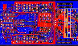
Soldering parts is a breeze... The boards are very good indeed
I guess I will have the boards populated in the end of the week.
These graphs are very important so I can visualize what will happen when tuning this part of the circuit.
My caps are too big so I will have to place some under the board
Soldering parts is a breeze... The boards are very good indeed
I guess I will have the boards populated in the end of the week.
Yes, the board solders well. It is even fun. Lets see who wins the competition and makes it work first. I am not the one. I am too busy with other things and i do not want to rush it.
Today i made a small change to my system. I am using a volume control pot in front of my power amps so i do not have a preamp. I build an ultra high speed class A preamp some time ago that sounds decent but i simply do not need it. That preamp goes up to 25MHz -3dB so making a volume control that goes up that high is not easy. A conventional pot has a lot of parasitics and over 500kHz it gets messy not to speak about more then 10 times that frequency. I solved it with a shunt pot where i am using a Charcroft naked Z Foil resistor as the series element. I even have a balance control that has very good channel separation up to high frequencies. Maybe i will tell you the trick how i solved that. That preamp told me that conventional pots do not cut the Mustard at very high frequencies so i was planning to modify my power amp accordingly for a long time. I am now using, just for fun, an older phono stage of mine. It is an ultra low noise, ultra low distortion one stage design that has a sizable amount of ultra low noise cascoded J_Fets at the input and is based on strong negative feedback. It was also my first attempt at a very low noise PSU. I got it quiet with a lot of effort but it is not that clever or efficient then the one that Frans designed for the paradise. I simply used brute force. The stage is super quit though. Ask Sam, he had it for quite a while. He claims that it is more quiet then the line stage i designed for him and that is quiet too. So technically all is good and fine. The sound of that stage is of the "monitoring" kind so it has no tendency to smooth over or candy tint at all. Some recordings can even sound a bit analytical and i had trouble on a very few very hot recordings with sibilance in the treble. The pot modification has reduced that effect now to a point where i can life with that stage very well. The mod sounds a bit more open and clean even but without adding sharpness. I have to listen more to get the full measure though.
Today i made a small change to my system. I am using a volume control pot in front of my power amps so i do not have a preamp. I build an ultra high speed class A preamp some time ago that sounds decent but i simply do not need it. That preamp goes up to 25MHz -3dB so making a volume control that goes up that high is not easy. A conventional pot has a lot of parasitics and over 500kHz it gets messy not to speak about more then 10 times that frequency. I solved it with a shunt pot where i am using a Charcroft naked Z Foil resistor as the series element. I even have a balance control that has very good channel separation up to high frequencies. Maybe i will tell you the trick how i solved that. That preamp told me that conventional pots do not cut the Mustard at very high frequencies so i was planning to modify my power amp accordingly for a long time. I am now using, just for fun, an older phono stage of mine. It is an ultra low noise, ultra low distortion one stage design that has a sizable amount of ultra low noise cascoded J_Fets at the input and is based on strong negative feedback. It was also my first attempt at a very low noise PSU. I got it quiet with a lot of effort but it is not that clever or efficient then the one that Frans designed for the paradise. I simply used brute force. The stage is super quit though. Ask Sam, he had it for quite a while. He claims that it is more quiet then the line stage i designed for him and that is quiet too. So technically all is good and fine. The sound of that stage is of the "monitoring" kind so it has no tendency to smooth over or candy tint at all. Some recordings can even sound a bit analytical and i had trouble on a very few very hot recordings with sibilance in the treble. The pot modification has reduced that effect now to a point where i can life with that stage very well. The mod sounds a bit more open and clean even but without adding sharpness. I have to listen more to get the full measure though.


But now Joachim !
You laugh them all out loud
Mr. Sonics
Audiofanatic
You laugh them all out loud
Mr. Sonics
Audiofanatic
I may be jealous for your bringing up. I was the one learning at school and the others got the chicks. The gils called me "Poti Hengst".
Audioholic
I didn't have any time for girl friends and other thing that all my other class mates where doing at that time. Like going to the disco etc.etc.
I was constantly making audio equipments better
When I med my lady, she was studying psychology and that was the time to wake up and realize that there is a lot more between heaven and earth
And we are still together for almost 27 years If Viv (the love of my life) didn't have the patience and knowledge to deal with and audio (electronic) addict, I'd be alone today so I think that is a blessing for both of us, to have a lady by your / my side and be like we (still) are audioholics.
atb,
José
Audiofanatic
I didn't have any time for girl friends and other thing that all my other class mates where doing at that time. Like going to the disco etc.etc.
I was constantly making audio equipments better
When I med my lady, she was studying psychology and that was the time to wake up and realize that there is a lot more between heaven and earth
And we are still together for almost 27 years
If Viv (the love of my life) didn't have the patience and knowledge to deal with and audio (electronic) addict, I'd be alone today so I think that is a blessing for both of us, to have a lady by your / my side and be like we (still) are audioholics.atb,
José
Audiofanatic
This is more interesting.
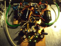
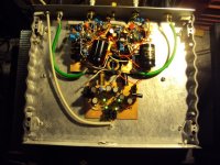
Photos of my current vinyl setup, the high speed pre and the JFet NFB phono.
Photos of my current vinyl setup, the high speed pre and the JFet NFB phono.
Attachments
I may be jealous for your bringing up. I was the one learning at school and the others got the chicks. The gils called me "Poti Hengst".
I bet the other guys now look 10 years older than you - are trapped in work they hate, have no skills, are afraid of tomorrow and have very 'blow dried' haircuts!!
Maybe.
The resistor i use now as the series element in the volume control of my poweramp are the 5kOhm Tantals you send me. So i have something from you in my sound.
These as you know come from Be originally!
But I am pleased, and am sure that he would approve of your dedication!