'Area 51' the amazing numbers (updated)
Today the man at the ‘Alien Technology Laboratory’, short ATL, are back from the party, they are now supplied with a nice, migraine like, headache. It seems that these man (from ATL) think better with the headache then with a party coming up (but boy do they like that enclosure).
They are sorry for the mistakes that crept in to the text posted message 4722 (http://www.diyaudio.com/forums/analogue-source/154210-mpp-473.html#post2873390). Also they improved there component choices, the circuits, as now presented, are more ‘real world’ applicable.
Any way here is there text:
======================================================
We are sorry, sorry, sorry, sorry, sorry (sorry for the mistakes …)
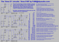
This ‘Alien Technology Laboratory’, short ATL, technology is freely available to anyone mad (or brave) enough to try it, use the attached files with care. When using any of these ATL, long ‘Alien Technology Laboratory’, findings please add an acknowledgement to ‘Area 51’-component and ATL to your project.
No further work/development will be done (on this subject) by the ATL department.
=-=-=-=-=-=-=-=-=-=-=-=-=-=-=-=-=-=-=-=-=-=-=-=-=-=-=-=-=-=-=-=-=-=
Circuit (B) is good for high current supplies (it is low drop)
Circuit (C) is good for low current supplies (good voltage regulation, low noise)
Additional benefits:
No need for inrush current protections
Less strain on the rectifier diodes (may enable better/nicer devices, lower price)
No strain on the mains fuse, fuse can a better match the application, and thus safer.
High frequency noise down (from 10 to 30dB).
=-=-=-=-=-=-=-=-=-=-=-=-=-=-=-=-=-=-=-=-=-=-=-=-=-=-=-=-=-=-=-=-=-=
Vout = 30V (as needed for the Paradise phone amp, with an bit of margin)
Iout = 150mA (one (mono) amp (left or right))
Rser(transformer) = 4 (taken from an actual 25V 15VA toroidal transformer)
Vripple = 5% = 1.5V (this determines the buffer capacitor size)
** 'Standard' circuit (A)
** ---------------------------------------------------------------------------------------------------------------------------
** The standard circuit voltage drop is 0.5V (the diode losses)
** (Transformer voltage(34.5Vpp) found by using simulator adjustments)
** Transformer voltage = 34.5Vpp / sqrt(2) = 25V(this is with some margin)
** Capacitor size(min) = 760uF (for 5% ripple, any larger value is allowed)
** Capacitor voltage specification = 34.5V * 2(spike margin) = 70V(63V is ok)
** 'Area 51' circuit (B)
** ---------------------------------------------------------------------------------------------------------------------------
** The 'Area 51'-drop voltage is (about) 2.3V
** (Transformer voltage(37Vpp) found by using simulator adjustments)
** Transformer voltage = 37Vpp / sqrt(2) = 26V(this is with some margin)
** Current controller RIset = 1.2Ohm (current set is 4 * 150mA = 600mA (about)).
** Capacitor size(min) = 900uF (for 5% ripple, any larger value is allowed)
** Capacitor voltage specification = 30V * 1.5(margin) = 45V <--- LOOK AT THAT!
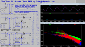
Above results with Vnoise.
The resulting capacitor charge time is 3 mS (5mS would be better)
To get a charge time of 5mS you need to change RIset.
This results in a lower output voltage, you must change the transformer voltage.
You can lower the buffer capacitor value.
** 'Area 51' circuit (C). Manually(simulator) tuned for 50% charging duty cycle
** ---------------------------------------------------------------------------------------------------------------------------
** The 'Area 51'-drop voltage is (about) 14V
** (Transformer voltage(47Vpp) found by using simulator adjustments)
** Transformer voltage = 47Vpp / sqrt(2) = 33V(this is with some margin)
** Current controller RIset = 2.2Ohm (current set is 2 * 150mA = 300mA (about)).
** Capacitor size(min) = 600uF (for 5% ripple, any larger value is allowed) <--- LOOK AT THAT!
** Capacitor voltage specification = 30Vout * 1.2(margin) = 36V(35V is ok) <--- LOOK AT THAT!
** (The more expensive transformer may be compensated by the cheaper capacitor)
Q1 and Q4, the Vceo must be (2 * Vtransformer-pp), Ic about 600mA, Hfe 10 or more.
(the TIP32C is a good match, mid power TO22, a bit low on Hfe, needs a heatsink attached)
Q2 and Q5, the Vceo must be (2 * Vtransformer-pp), Ic about 200mA, Hfe 10 or more.
(the MPSL51 is a good match, low power TO92)
Q3 and Q6, the Vceo must be (2 * Vtransformer-pp), Ic about 200mA, Hfe 50 or more.
(the MPSL51 is a good match, low power TO92, a bit low on (min)Hfe)
The way this works is simple, set RIset to control the maximum current, for
configuration (A) the current set should be 4 * Iout(average), for the 50%
duty cycle configuration (B) this should be 2 * Iout(average).
The transformer voltage sets the time that current is being supplied, this
time set the average voltage on the output capacitor. Due to the fact
that configuration (B) only delivers current for 50% of the time, the
voltage selected will be relatively high.
The rules and figures are general 'ballpark' rules. The best way to select the
components needed is by using a simulator (like LTspice from
Linear Technology Corporation's).
======================================================
Regards,
Under NDA for ATL
Frans.
Original version contains some errors
Today the man at the ‘Alien Technology Laboratory’, short ATL, are back from the party, they are now supplied with a nice, migraine like, headache. It seems that these man (from ATL) think better with the headache then with a party coming up (but boy do they like that enclosure).
They are sorry for the mistakes that crept in to the text posted message 4722 (http://www.diyaudio.com/forums/analogue-source/154210-mpp-473.html#post2873390). Also they improved there component choices, the circuits, as now presented, are more ‘real world’ applicable.
Any way here is there text:
======================================================
We are sorry, sorry, sorry, sorry, sorry (sorry for the mistakes …)
This ‘Alien Technology Laboratory’, short ATL, technology is freely available to anyone mad (or brave) enough to try it, use the attached files with care. When using any of these ATL, long ‘Alien Technology Laboratory’, findings please add an acknowledgement to ‘Area 51’-component and ATL to your project.
No further work/development will be done (on this subject) by the ATL department.
=-=-=-=-=-=-=-=-=-=-=-=-=-=-=-=-=-=-=-=-=-=-=-=-=-=-=-=-=-=-=-=-=-=
Circuit (B) is good for high current supplies (it is low drop)
Circuit (C) is good for low current supplies (good voltage regulation, low noise)
Additional benefits:
No need for inrush current protections
Less strain on the rectifier diodes (may enable better/nicer devices, lower price)
No strain on the mains fuse, fuse can a better match the application, and thus safer.
High frequency noise down (from 10 to 30dB).
=-=-=-=-=-=-=-=-=-=-=-=-=-=-=-=-=-=-=-=-=-=-=-=-=-=-=-=-=-=-=-=-=-=
Vout = 30V (as needed for the Paradise phone amp, with an bit of margin)
Iout = 150mA (one (mono) amp (left or right))
Rser(transformer) = 4 (taken from an actual 25V 15VA toroidal transformer)
Vripple = 5% = 1.5V (this determines the buffer capacitor size)
** 'Standard' circuit (A)
** ---------------------------------------------------------------------------------------------------------------------------
** The standard circuit voltage drop is 0.5V (the diode losses)
** (Transformer voltage(34.5Vpp) found by using simulator adjustments)
** Transformer voltage = 34.5Vpp / sqrt(2) = 25V(this is with some margin)
** Capacitor size(min) = 760uF (for 5% ripple, any larger value is allowed)
** Capacitor voltage specification = 34.5V * 2(spike margin) = 70V(63V is ok)
** 'Area 51' circuit (B)
** ---------------------------------------------------------------------------------------------------------------------------
** The 'Area 51'-drop voltage is (about) 2.3V
** (Transformer voltage(37Vpp) found by using simulator adjustments)
** Transformer voltage = 37Vpp / sqrt(2) = 26V(this is with some margin)
** Current controller RIset = 1.2Ohm (current set is 4 * 150mA = 600mA (about)).
** Capacitor size(min) = 900uF (for 5% ripple, any larger value is allowed)
** Capacitor voltage specification = 30V * 1.5(margin) = 45V <--- LOOK AT THAT!
Above results with Vnoise.
The resulting capacitor charge time is 3 mS (5mS would be better)
To get a charge time of 5mS you need to change RIset.
This results in a lower output voltage, you must change the transformer voltage.
You can lower the buffer capacitor value.
** 'Area 51' circuit (C). Manually(simulator) tuned for 50% charging duty cycle
** ---------------------------------------------------------------------------------------------------------------------------
** The 'Area 51'-drop voltage is (about) 14V
** (Transformer voltage(47Vpp) found by using simulator adjustments)
** Transformer voltage = 47Vpp / sqrt(2) = 33V(this is with some margin)
** Current controller RIset = 2.2Ohm (current set is 2 * 150mA = 300mA (about)).
** Capacitor size(min) = 600uF (for 5% ripple, any larger value is allowed) <--- LOOK AT THAT!
** Capacitor voltage specification = 30Vout * 1.2(margin) = 36V(35V is ok) <--- LOOK AT THAT!
** (The more expensive transformer may be compensated by the cheaper capacitor)
Q1 and Q4, the Vceo must be (2 * Vtransformer-pp), Ic about 600mA, Hfe 10 or more.
(the TIP32C is a good match, mid power TO22, a bit low on Hfe, needs a heatsink attached)
Q2 and Q5, the Vceo must be (2 * Vtransformer-pp), Ic about 200mA, Hfe 10 or more.
(the MPSL51 is a good match, low power TO92)
Q3 and Q6, the Vceo must be (2 * Vtransformer-pp), Ic about 200mA, Hfe 50 or more.
(the MPSL51 is a good match, low power TO92, a bit low on (min)Hfe)
The way this works is simple, set RIset to control the maximum current, for
configuration (A) the current set should be 4 * Iout(average), for the 50%
duty cycle configuration (B) this should be 2 * Iout(average).
The transformer voltage sets the time that current is being supplied, this
time set the average voltage on the output capacitor. Due to the fact
that configuration (B) only delivers current for 50% of the time, the
voltage selected will be relatively high.
The rules and figures are general 'ballpark' rules. The best way to select the
components needed is by using a simulator (like LTspice from
Linear Technology Corporation's).
======================================================
Regards,
Under NDA for ATL
Frans.
Attachments
Last edited:
No, not yet
Thanks, My boards arived (in good nick). The package is marked:
PRIORITY
(LUFTPOST)
They are very, verry ... nice.
Attachments

Last edited:
Thanks, My boards arived (in good nick). The package is marked:
PRIORITY
(LUFTPOST)
They are very, verry ... nice.
good to know. please share how you like the soldering - the finish is galvanic silver so its supposed to be good
good to know. please share how you like the soldering - the finish is galvanic silver so its supposed to be good
That has to wait a while, this week there is no time, next weekend I am gone
, the week there after I am finishing my 'SSA BIG4BT V2'. If other people have problems with the power supply I will be using my vero-board beta for testing.Regards,
Frans.
It is approximate 1000x times of the input impedance of the RIIA @ 1kHz. So you can simulate the input impedance of the RIIA and interpolate from that. This is for both mirrors ( positive and negative ) in parallel so one mirror alone has double that output impedance. The output impedance of the two mirrors in parallel divided by the input impedance of the RIIA gives the gain. @ 1kHz it is a bit over 60dB.
That is what I was afraid of... it changes with frequency... maybe you could simulate it for 1kHz only for calculation purposes.
IMO I must choose the riaa parts very acurately because any small change will create great deviations from riaa standard and I need to start with the mirror output imp in the first place.
IMO I must choose the riaa parts very acurately because any small change will create great deviations from riaa standard and I need to start with the mirror output imp in the first place.
Yes, it is a dynamic "electronic" output impedance. This phono is fast, very fast, but even here there is a boundary at very high frequency. It does not affect the subjective performance in any way. I can measure the RIIA curve exact only to 500kHz and up to there i can see no deviation. There is no information on the record over say 50kHz anyway and if, it is from scratches, dirt, miss tracking and such. Fortunately all this is shunted to ground by the two 6,8nF caps so you will experience that this "noise" is very much confined to a diffuse field near the speakers and does not appear in the sound field. I call this "source separation" or "protection technology". You will also experience that scratches "sound" very "short" and "small" like coming from an infinity small point in space. In the subsonic area we have a limited output impedance too but i do not think that it is a good idea to have infinite gain at DC.
Yes, at 20Khz your 305,7KOhm seems just about right. I can see no reason that this RIAA should not be exact though. With the values given RIAA simulates accurate to plus-minus 0,3dB with the biggest deviation in the bass. Anything better must be trimmed to the actual circuit anyway. Plus-Minus 0.1dB is possible but then you have to trim each and every position. What i think is even more important that both channels match closely because that has consequences on the imaging. But then you really need an extremely good combination of turntable - arm - and very much the cartridge. Has any one a cartridge that is in the Plus - Minus 0.1dB class ?
Another argument Ricardo. At higher frequencies the impedance of the RIIA goes ultimately to Zero Ohm ( actually the loss in the cap is the limit ), so the higher you go the less critical the output impedance of the current mirror is. The precision of this circuit in the treble is excellent. By the way building the circuit different from Hesener ( after i have approved to it ) will give a different
result so it is not a Paradise any more in the pure sense, like it or not.
result so it is not a Paradise any more in the pure sense, like it or not.
Here you can read about it :Das Leben des Klangmeisters - Von Röhren über Sand bis Wirkungsgrad