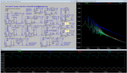
this is the only chritical piont as i see it....reason is that even small differences in the mirror resistors will cause the the riaa circuit offset values to slide up and down, as a product of the mirror output impedance (which is big) and of the combined DC impedance of the RIAA network and buffer impedance. even 1 ohm makes a big differnence...So this for sure needs some trimming. 10K trimmer i both positions would not be bad....
The buffer has a permanent -15 mV offset (in my simulations) which is corrected by the servo, So it could be a good idea to adjust the RIAA node to app +15 mV or simply 0 mV after the buffer")
So trimmer pads can be welcome, and its value or very use of it or not can be an open option decided on initial behavior (BJTs matching level reasons in each build etc.).
I found a silicon carbide diode that is semi affordable :C4D02120A Cree, Inc. Schottky (Diodes & Rectifiers)
To the best my knowledge the place to balance the circuit i by adjusting the current-mirror resistor...the servo does the same, but it dose so changing the currents through all stages, this resistor adjustment just balance's th circuit by compensating for the gain differences in NPN PNE transistors. The servo can then take care of the thermal drift.
Bksabath, what schematic are you using ?
I miss the common mode coils.
Beter?
My PCB software has a poor library and I am using Pads
(RS has free download with much beter components library and same functionality.)
I have used 5 mm MKP outline for the 100 nF
I left the ground pads for the output capacitors out those can be aded at any time.
Probably someone will use Mundorf silver in oil there
and those are preaty big.Just noticed mistake in the Farnell book that spec coil at 100mH
On the intraweb catalog is clearly 100uM
would it be possible to arrange group buy for comon mode coils please?
I will rewiew PCB with exact size ASAP
Attachments
Last edited:
I have published that before but i do it again :
This is the common mode choke i am using :CAF 0,6-100 - Stromkompensierte Drossel, 100mH, 20 - 30mm - Stromkompensierte Drosseln bei reichelt elektronik
We could organize a group buy.
This is the common mode choke i am using :CAF 0,6-100 - Stromkompensierte Drossel, 100mH, 20 - 30mm - Stromkompensierte Drosseln bei reichelt elektronik
We could organize a group buy.
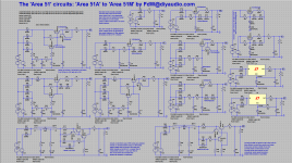
'Area 51' the rogue edition
Dear All,
Although our ‘Alien Technology Lab’, short ATL, did say that they would stop working on the 'Area 51' circuit, it seems that some rogue developer(s) continued there obsessive analysis efforts.
The results, of the new (unofficial, rogue edition) ATL efforts must be kept secret (jobs may depend on this), so please keep this information to yourself (don not let it out in the open).
Attached is the extended ATL circuit collection (circuits L and M added).
This ATL technology is freely available to anyone mad (or brave) enough to try it, use the attached files with care. When using any of these ATL findings please add an acknowledgement to ‘Area 51’-component and ATL to your project.
Regards,
Acting for ATL,
Frans.
Dear All,
Our ‘Alien Technology Lab’, short ATL has been working on variations of the ‘Area 51’ component. The result of the ATL work is attached to this message. Early ATL results show that the performance of the standard circuit can be improved by up to 50 dB (in the early ATL prototypes).
This ATL technology is freely available to anyone mad (or brave) enough to try it, use the attached files with care. When using any of these ATL findings please add an acknowledgement to ‘Area 51’-component and ATL to your project.
No further work/development will be done (on this subject) by the ATL department.
Questions will be answered in this forum.
Regards,
Acting for ATL,
Frans
Attachments
Last edited:
Pre regulator PCB
Common mode to spek 20X30 pin out
100 nF caps 5 mm foot print
Beter?
I have used 1mm thick tracks agin this can be changed
This is starting to look real nice. One thing I would like to see changed, make the tracks a bit wider, this would make the board also usable beyond 150 mA (maybe up to 2 or 3 amps).
This has the footprint http://www.reichelt.de/Bauelemente/...8AAAIAAF6RXbceaa3f6c4862b3f1a256175882e8ff34c
And there are other variations (with more mH's then this one (but less than the first one)) that would fit in that footprint.
Regards,
Frans.
Last edited:
Frans, i like the ones with the switched coils. Do you need a microprocessor to steer this ?
The intention is to have them permanent on (in place) (is what the people at the ATL tell me). The reason for the switches is to remove them from the circuit for performance measurements (it would not be fair to the other circuits, tells one of the ATL developers).
The intention is to have them permanent on (in place) (is what the people at the ATL tell me). The reason for the switches is to remove them from the circuit for performance measurements (it would not be fair to the other circuits, tells one of the ATL developers).
And yes, maybe they (the ATL people) use a 'main frame' (or even microcomputer) to control this
Actual current ATL hardware
Last edited:
Hi Frans
Tanks
Wider traks
Agree with you on that.
I was also looking at the track going to Q3 and Q7 In my drawing which is a bit long.
To keep cost down and ease of home brew I would like to keep the single sided board.
Would a wire Jumper bee too bad?
Another thing that may be looking up is the choice of capacitors.
The MKP 1837 has a pitch of 5 mm.
There are alternatives such as the MKP B32625 Epcos, MKP375 BCcomponents,MKP378
those have pitch of 22.5 mm (Farnell stock)
Changing from 5.5 to 22.5 for Your SCH C15/C18/C19/C22 would alowd for much larger tracks
Altrought with the 5 mm pitch those could and will be increased to at least 2 mm.
Don't worry about putting things forward I don't mind making any changes as needed.
And got refilable cartriges on printer...
Bksabath, what kind of electrolytics are you planning ?
I usually use Panasonic FM but others like Rubicon, Nichicon, Frotyth etc. will work well too and should have the same footprint.
Any shape and sizes can be used as you wish There is plenty of space on the board
As one of the pins on both sides is to ground al needed is placing a pad on the ground plane.
Eventualy we need to consider the board size to reduce waste but still early for that
Hi Frans
Tanks
Wider traks
Agree with you on that.
I was also looking at the track going to Q3 and Q7 In my drawing which is a bit long.
To keep cost down and ease of home brew I would like to keep the single sided board.
Would a wire Jumper bee too bad?
Another thing that may be looking up is the choice of capacitors.
The MKP 1837 has a pitch of 5 mm.
There are alternatives such as the MKP B32625 Epcos, MKP375 BCcomponents,MKP378
those have pitch of 22.5 mm (Farnell stock)
Changing from 5.5 to 22.5 for Your SCH C15/C18/C19/C22 would alowd for much larger tracks
Altrought with the 5 mm pitch those could and will be increased to at least 2 mm.
Don't worry about putting things forward I don't mind making any changes as needed.
And got refilable cartriges on printer...
I would like a dual sided board, when home brew (single sided) you would do the bottom layer only and have one or two jumpers; otherwise they would go on the top side. Having two sides you would use the top side as a ground plane. How would that be?
The MKP's would be fine with me, but my say on capacitors should not be definite