Lme49990
Joachim, here is another candidate for lowest noise & lowest THD: the LME49990.
THD < 0.00002 at 20kHz, PSRR > 100dB at 20kHz.
Blows your mind.
http://www.national.com/ds/LM/LME49990.pdf
jd
Joachim, here is another candidate for lowest noise & lowest THD: the LME49990.
THD < 0.00002 at 20kHz, PSRR > 100dB at 20kHz.
Blows your mind.
http://www.national.com/ds/LM/LME49990.pdf
jd
Thats fine. They come quicker then i can purchase them, not to mention build anything.
We could organise a shoutout at Jan. AD against National.
Anyway, the way i use the AD makes distotion so low ( shunt feedback) that audible differences will be very small. I have not studied the National enough if it can drive a feedback resistor lower then 600 Ohm. In that case, using the Phonoclone topology you have to burn a lt of amplification in a resistive devider.
You would need super exact capacitors and resistors so to have any tight tolerance curve check meaning. Tough without a lab grade calibrated bridge to select. It can simply compound with de-emphasis tolerances and even out or boost a curve trend erratically, If it does not have seriously better selected components than what it feeds. Maybe it will be practical to tune it against a text book Riaa emphasis curve graphically on the FFT than to be sure about parts values. Just an idea.
Usually i work with a mathematically generated curve in my DAAS analyser.
This is not awailable at the moment out of known resons.
I selected the parts by using 0.01% reference resistors and 0.1% reference caps.
My bridge shows values that are 99.9 kOhm for a 100kOhm resistor and 9.9nF for a 10nF cap. I interpolated the values and trimmed with 1% silver mica. That is the best i can do at home. Lets see what happens because the mathematics of the Self RIAA are indisputable.
I am planning on an aditinal balanced input for The JG Self.
The topolohy is an inamp made from Op amps.
I made the resistor values as low as i could to avoid noise. The LME49990 can drive 20mA clean so with the choosen values i get 3V max output. That is ample for a Pre-Pre.
Noise should be around 1.4nV / qHz
Attachments
Hi Joachim, Jan,
I'm gonna order a few LME49990 and make a nice little amp with them and will post my result when ready.
Thanks for the info!
Best regards,
Audiofanatic")
José, I don't think they have samples available yet.
jd
Samples
Hi Jan,
I've ordered a few samples yesterday and will have them within a few day's!
So If you want to try them out, just log in and order them asap.
These OPAmp's looks Goooooooood
Gr,
Audiofanatic
José, I don't think they have samples available yet.
jd
Hi Jan,
I've ordered a few samples yesterday and will have them within a few day's!
So If you want to try them out, just log in and order them asap.
These OPAmp's looks Goooooooood
Gr,
Audiofanatic
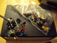
I have not posted for a while because i was very bussy building the RIAA Encoder and make it work reliably and precise. That was bigger of a task that this seemingly simple circuit sugests. Finding precise resistors and caps was not easy. I have no problem measuring them to better precission then 0.5% but i got a bit fanatic and had to drive into town many times to buy some and get some from a friend. It is now a wild combination of Wima FKP1, Silver Mica, Dale RS55 and normal 1% metalfilm that i selected out of my waiste bin.
Then i ran into trouble with the servo and then the second amplification stage did not work. The mistake was so ambarassing stupid that i spare you the details. I looked several hours into the box and could not find it. Let me say so much that building this out of double OPamps was not a good idea. After i got it working i found that measuring at that low level over such a wide bandwidth is a challange in itself.
Some hours ago i got it finally working and have first results.
I measured the High Z MPP with Inductive RIAA and in the audible band i found very similar results then what i had measured over the DAAS. The DAAS limits measurements to 20kHz and one of the advantages of this encoder is that i can measure over a much wider high frequency bandwidth.
One very telling test is a 1kHz or even 10kHz quarewave. In an ideal situation the combination of Encoder and RIAA gives a perfectly quare quarewave.
What i found with the Inductive RIAA is a 7dB overshot at over 400kHz. If that is the result of the Encoder or the Inductive RIAA itself i will find out tomorrow.
For other purposes i had build a little wideband linear measurement amp from an OPA627 that should be very flat to over 10Mhz. With that amp and my Sennheiser Tube
Voltmeter i will test the setup.
My next post shows some pictures i collected over the last hours.
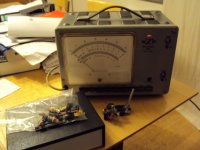
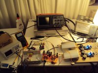
Here some pictures. First the measurement setup.
From left : DSD generator, RIAA Encoder in small metall box. 40MHz Digital Scope,
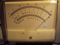
Sennheiser Tube True RMS Meter ( bandwidth 1MHz)
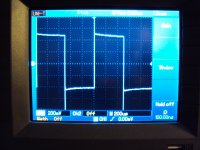
1kHz Quarewave over Encoder, High Z Mpp - Inductive RIAA
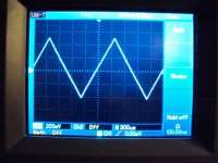
1kHz Triangle .... same...
From left : DSD generator, RIAA Encoder in small metall box. 40MHz Digital Scope,
Sennheiser Tube True RMS Meter ( bandwidth 1MHz)
1kHz Quarewave over Encoder, High Z Mpp - Inductive RIAA
1kHz Triangle .... same...
Attachments
I try one more time.
Left: Level at 200kHz
Right: Level at 1kHz
Well uploading does does not work. I try again tomorrow.
Thinking more about the ringing at 450kHz i think the reason is in the Encoder.
The opamp will reach its output swing at some point higher up and then a forth time constant is established.
I will look into that in more depth when i find the time.
Until 100kHz everything seems ok.