I never say anything like my design is better than others.
But for those few who bothered to build one, they all love it.
Especially if you have a low impedance can (like Grado or AKG), which the HD555 probably isn't.
Not that it will sound bad on a 555, but you are not using its current delivery capability to the full.
Patrick
But for those few who bothered to build one, they all love it.
Especially if you have a low impedance can (like Grado or AKG), which the HD555 probably isn't.
Not that it will sound bad on a 555, but you are not using its current delivery capability to the full.
Patrick
@Dr.H: Grado usually is 32ohm. AKG depend on models, 62ohm to 120ohm.
HD555 at 50ohm should be fine too... HD555 (and most Sennheiser phones) is not a current hungry phones
It is not the impedance itself, but the combination of low impedance + lower sensitivity that makes Grado and AKG need more current to really sing. While Sennheiser phones are usually highly sensitive (+ high impedance on the HD600 and above models)
Copied my question from here to here...
@Patrick: sorry, for the very basic questions:
1. is this a unity gain amp (or not)?
2. could I put a potentiometer in the input?
3. what is the [maximum] acceptable preceding stage (source or pre-amp) impedance before the DAO?
thanks,
David
@Patrick: sorry, for the very basic questions:
1. is this a unity gain amp (or not)?
2. could I put a potentiometer in the input?
3. what is the [maximum] acceptable preceding stage (source or pre-amp) impedance before the DAO?
thanks,
David
I am reviving this ancient thread as it appears the DAO is just what I need for my Grados and I already have a nice preamp.
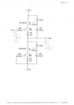
If I use this schematic (replacing IRFP240 for the toshiba mosfets), do the IRFs need to be matched to maintain low DC offset?
Are all resistors 1/4W except for the 3R/3W?
Any substitute for the J511? It's obsolete.
8.2V Zener is 5W OK?
Thank you Patrick, if you see this.
If I use this schematic (replacing IRFP240 for the toshiba mosfets), do the IRFs need to be matched to maintain low DC offset?
Are all resistors 1/4W except for the 3R/3W?
Any substitute for the J511? It's obsolete.
8.2V Zener is 5W OK?
Thank you Patrick, if you see this.
Attachments
Did you see this ?
http://www.diyaudio.com/forums/head...se-all-fet-class-zgf-headphone-amplifier.html
Patrick
http://www.diyaudio.com/forums/head...se-all-fet-class-zgf-headphone-amplifier.html
Patrick
Did you see this ?
http://www.diyaudio.com/forums/head...se-all-fet-class-zgf-headphone-amplifier.html
Patrick
Thank you Patrick. This is perfect. Looks like the info on the Dao got spread out over a couple threads but I trying to understand it all now. Interesting use of that power jfet...actually it's pretty genius. Thanks.
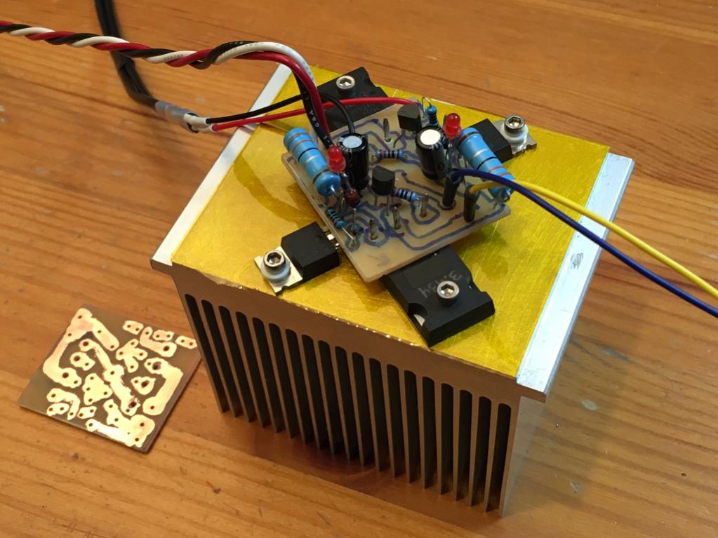
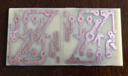
Wow, a year has past since the last post here. I decided to give the DAO SE head amp a try. I like simple circuits. Anyhow, this is a first for me - my first ever home etched PCB! I used Uncle Carlos' trick (Destroyer X) of using nail polish to directly hand paint the traces by eye. It looks rough but turned out very functional. I hand drilled the holes with Dremel tool. Muriatic acid and hydrogen peroxide made quick work of the etching and in less than an hour I had a pair of my first hand made PCBs. ") Thanks to EUVL for the layout and Steen for the inspiration to make it work. Normally I would just deadbug P2P this but wanted to try etching on a simple project.
Thanks to EUVL for the layout and Steen for the inspiration to make it work. Normally I would just deadbug P2P this but wanted to try etching on a simple project.
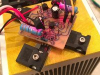
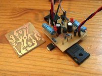
So here is one board soldered up and mounted on a Pentium CPU heatsink designed for 60w with a fan (I plan to use a small speed reduced fan):
I was anxious to build something while waiting for ordered parts to arrive (LU1014 & J511, 8.3v zener). So I made some substitutions hoping something might work.
I am using a J310 JFET with gate tied to source for the constant current supply (they are 10mA capable) and since I do not have 8.3v zeners I am using 6.8v zener plus a red LED in series to get about same voltage drop. The big one is using an IRF610 in place of a the LU1014 JFET - I have no idea if this can even work but seems like it might.
I did not have my 25v class A supply handy so used the 21v supply from another project that was currently connected for a quick test. LEDs light up but the bias is all wrong as there is no current flowing. Checking gate voltage I only got 5.3v? Strange as a 6.8v drop across the zener plus 1.8v across the LED (after the zener) should present an 8.6v before the zener to drive the IRFP240 gate (through 220R). More debugging needed but at least no magic smoke was emitted and no FETs were harmed in the process. (actually, all these FETs were pulls from my failed allfet Circlotron build - tested to be functional in my new Vgs tester):
So a few questions:
1. what is ideal zener voltage to use for IRFP240 to get 200mA bias?
2. can an IRF610 serve in place of LU1014 to make some music?
3. how closely do the Vgs values of both the IRFP's and LU1014's have to be matched or can we get by with adjusting source resistors by adding small parallels?
Thanks to EUVL for the layout and Steen for the inspiration to make it work. Normally I would just deadbug P2P this but wanted to try etching on a simple project.So here is one board soldered up and mounted on a Pentium CPU heatsink designed for 60w with a fan (I plan to use a small speed reduced fan):
I was anxious to build something while waiting for ordered parts to arrive (LU1014 & J511, 8.3v zener). So I made some substitutions hoping something might work.
I am using a J310 JFET with gate tied to source for the constant current supply (they are 10mA capable) and since I do not have 8.3v zeners I am using 6.8v zener plus a red LED in series to get about same voltage drop. The big one is using an IRF610 in place of a the LU1014 JFET - I have no idea if this can even work but seems like it might.
I did not have my 25v class A supply handy so used the 21v supply from another project that was currently connected for a quick test. LEDs light up but the bias is all wrong as there is no current flowing. Checking gate voltage I only got 5.3v? Strange as a 6.8v drop across the zener plus 1.8v across the LED (after the zener) should present an 8.6v before the zener to drive the IRFP240 gate (through 220R). More debugging needed but at least no magic smoke was emitted and no FETs were harmed in the process. (actually, all these FETs were pulls from my failed allfet Circlotron build - tested to be functional in my new Vgs tester):
So a few questions:
1. what is ideal zener voltage to use for IRFP240 to get 200mA bias?
2. can an IRF610 serve in place of LU1014 to make some music?
3. how closely do the Vgs values of both the IRFP's and LU1014's have to be matched or can we get by with adjusting source resistors by adding small parallels?
Attachments

Zener voltage should not influence current much at all. That is mainly determined by LU1014 Idss and gm and the 3R source resistor down in the current source.1. what is ideal zener voltage to use for IRFP240 to get 200mA bias?
No, not as-is. You need a depletion mode device in the current source, IRF610 is a typical MOSFET in that it is enhancement mode and as such doesn't bother conducting much at all at Vgs=0.2. can an IRF610 serve in place of LU1014 to make some music?
I have little experience matching FETs, but this should work for a first-order approximation at least. You'll be able to match gm at DC, parasitic capacitance may be a different story.3. how closely do the Vgs values of both the IRFP's and LU1014's have to be matched or can we get by with adjusting source resistors by adding small parallels?
No, not as-is. You need a depletion mode device in the current source, IRF610 is a typical MOSFET in that it is enhancement mode and as such doesn't bother conducting much at all at Vgs=0.
Thanks - that explains why I am not getting any bias current. I will have to wait for those LU1014's now...
Wow, a year has past since the last post here. I decided to give the DAO SE head amp a try. I like simple circuits. Anyhow, this is a first for me - my first ever home etched PCB! I used Uncle Carlos' trick (Destroyer X) of using nail polish to directly hand paint the traces by eye. It looks rough but turned out very functional. I hand drilled the holes with Dremel tool. Muriatic acid and hydrogen peroxide made quick work of the etching and in less than an hour I had a pair of my first hand made PCBs.
Nicely done. So finally tired of paying Chinese board houses and then waiting for a long time anxiously, are we
?Well for simple projects at this point it's fun to try and make a board. But man, my work is fugly. I really like how nice a pro made board looks and is easy to assemble with good silk screen. Maybe for shunt regulators or cap multiplier it is a good option. Certainly for simple amp like this single ended class A it was worth a try. I will try Still4given's technique for iron on transfers next and see how far I get.
Progress
My LU1014D's were waiting for me when I got back from travel today. I installed them into my handmade PCBs and did a few tests with 10R safety resistors in the PSU rails to make sure nothing would smoke. Looked good so I put the power in direct. I am using a 100VA 15V (Antek AS-1215) and the FW standard PSU with 33mF//0.125R//33mF CRC. The amp is now drawing 330mA (1.09v across 3.3R) and the offset is a steady 22mV. The bias current is also steady. This is a pretty good DC offset actually given that there was no attempt to match the LU1014D's yet (actually I did try to but the rig I have built for measuring Idss on my 2SK170's doesn't seem to work here). So rails are about 20v and ripple at rail was measured to be 6mV.
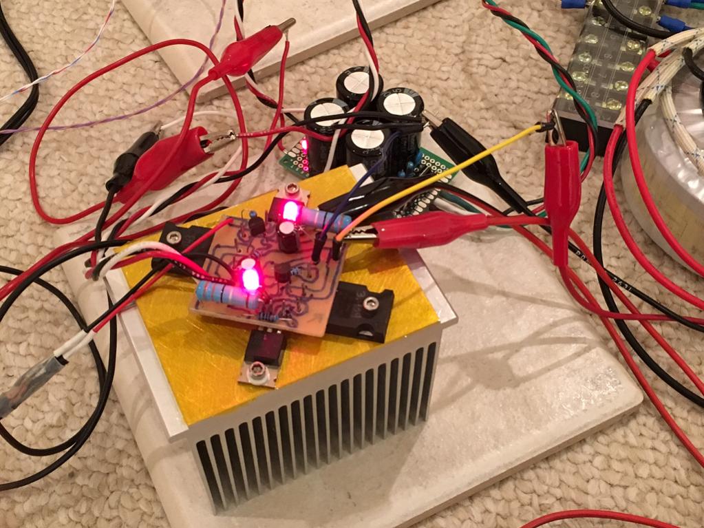
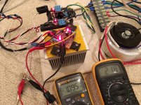
Here is a photo of the amp and PSU in action, you can see the reading on the bias current on the left DMM and the right one is the DC offset:

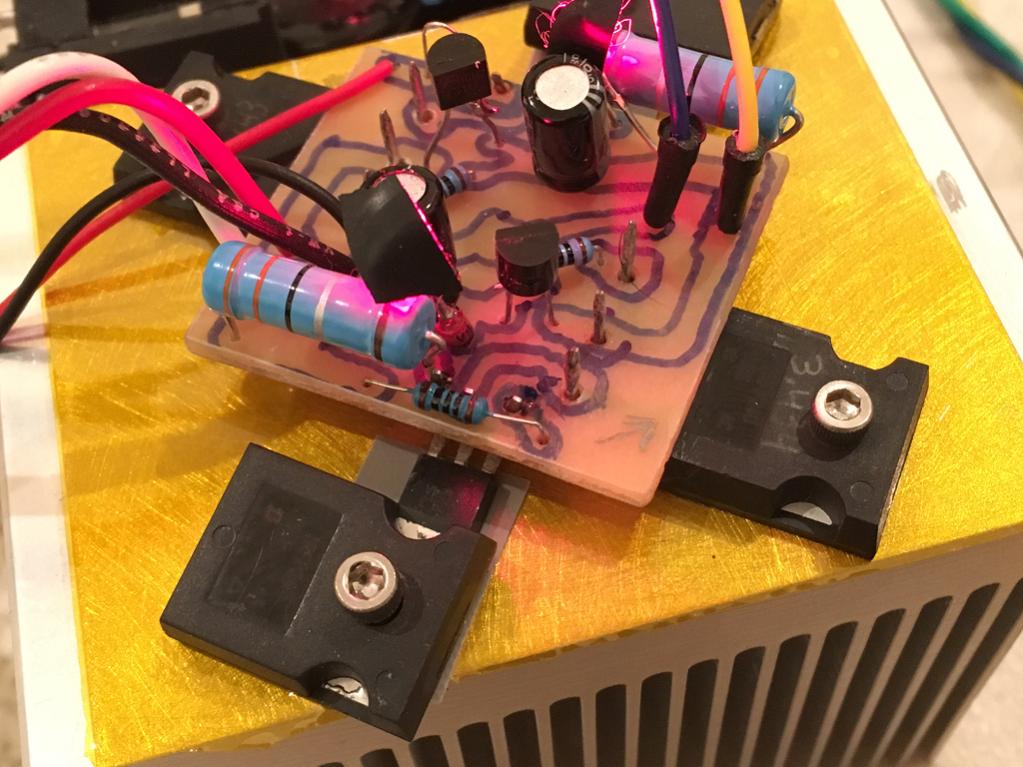
Here is a closeup of the amp itself (tape is used to block red glare from LEDs). I am using dead IRFP bodies as clamp bars to hold the LU1014D pressed against the heatsink with silicone insulator sheet:
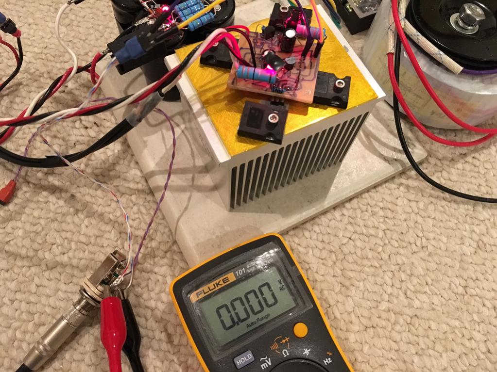
Using my Sony MDRV6 on one channel and driven by XMOS U8/Burr Brown PCM5102A DAC - the sound is very nice. Not high enough SPL but that is because the DAC is only driven at 5v. With a more powerful opamp driver DAC or a preamp I think the volume could be made greater. As it is, a bit soft however what I hear sounds really nice. What is very interesting is that even with the DAC attached and a PSU that has 6mV ripple, the amp is dead silent (no hiss or hum whatsoever) when music is not playing. Cannot tell it is on - so very nice. This amp has good PSRR as evidenced here in measurement of output noise with Fluke 101 at 0.0mV ac:
I could use a higher voltage PSU and then add a cap multiplier and it will be even quieter (although already inaudible). It is definitely a class A heater though - heatsink is disspating about 13w and is pretty toasty without a fan.
I know my hand drawn PCB is pretty fugly so when I get a chance, I will switch over to a PDF transfer but still hand etched PCB that I now have. This was made using vinyl transfer film and laser printer:

My LU1014D's were waiting for me when I got back from travel today. I installed them into my handmade PCBs and did a few tests with 10R safety resistors in the PSU rails to make sure nothing would smoke. Looked good so I put the power in direct. I am using a 100VA 15V (Antek AS-1215) and the FW standard PSU with 33mF//0.125R//33mF CRC. The amp is now drawing 330mA (1.09v across 3.3R) and the offset is a steady 22mV. The bias current is also steady. This is a pretty good DC offset actually given that there was no attempt to match the LU1014D's yet (actually I did try to but the rig I have built for measuring Idss on my 2SK170's doesn't seem to work here). So rails are about 20v and ripple at rail was measured to be 6mV.
Here is a photo of the amp and PSU in action, you can see the reading on the bias current on the left DMM and the right one is the DC offset:
Here is a closeup of the amp itself (tape is used to block red glare from LEDs). I am using dead IRFP bodies as clamp bars to hold the LU1014D pressed against the heatsink with silicone insulator sheet:
Using my Sony MDRV6 on one channel and driven by XMOS U8/Burr Brown PCM5102A DAC - the sound is very nice. Not high enough SPL but that is because the DAC is only driven at 5v. With a more powerful opamp driver DAC or a preamp I think the volume could be made greater. As it is, a bit soft however what I hear sounds really nice. What is very interesting is that even with the DAC attached and a PSU that has 6mV ripple, the amp is dead silent (no hiss or hum whatsoever) when music is not playing. Cannot tell it is on - so very nice. This amp has good PSRR as evidenced here in measurement of output noise with Fluke 101 at 0.0mV ac:
I could use a higher voltage PSU and then add a cap multiplier and it will be even quieter (although already inaudible). It is definitely a class A heater though - heatsink is disspating about 13w and is pretty toasty without a fan.
I know my hand drawn PCB is pretty fugly so when I get a chance, I will switch over to a PDF transfer but still hand etched PCB that I now have. This was made using vinyl transfer film and laser printer:
Attachments

Last edited:
I connected both of my headphones to single output (30R impedance) and wow! the bass really went up - so this amp is really meant for low impedance headphones as stated earlier. It really has some authority now.
Some sad news: I had one of the J310's go out on me with my left headphone in place and it saw 14v.6 Damaged driver on left channel now makes a clicking sound. Anyhow, headphone protection circuit is a must. I soldered in a pair of back-back 4.2v zeners between the headphone outs (at the jack) as a safety measure from frying my other side. The sound is still very nice - why don't we use back-to-back zeners as simple headphone protections? The actual audio is always under 1v and maybe a 2v zener may be better but I know my headphones have taken 4v for a few seconds before without damage and that is the lowest value I have at present. That was a $40 mistake to get a replacement driver for my headphones.
Anyhow, back to the bass: it is stunning when running low impedance. The amp really has some guts.
Still noiseless, no hum, no hiss. Dead dead silent and no regulation or cap multiplier needed. I do have a hefty 33mF//0.125R//33mF PSU though.
When heatsink is placed on side so fins can flow vertically, heat output is manageable without a fan. Now at thermal steady state the DC offset is 17mV. Very acceptable and not sure if worth trimming by paralleling power resistors?
Some sad news: I had one of the J310's go out on me with my left headphone in place and it saw 14v.6
Damaged driver on left channel now makes a clicking sound. Anyhow, headphone protection circuit is a must. I soldered in a pair of back-back 4.2v zeners between the headphone outs (at the jack) as a safety measure from frying my other side. The sound is still very nice - why don't we use back-to-back zeners as simple headphone protections? The actual audio is always under 1v and maybe a 2v zener may be better but I know my headphones have taken 4v for a few seconds before without damage and that is the lowest value I have at present. That was a $40 mistake to get a replacement driver for my headphones.Anyhow, back to the bass: it is stunning when running low impedance. The amp really has some guts.
Still noiseless, no hum, no hiss. Dead dead silent and no regulation or cap multiplier needed. I do have a hefty 33mF//0.125R//33mF PSU though.
When heatsink is placed on side so fins can flow vertically, heat output is manageable without a fan. Now at thermal steady state the DC offset is 17mV. Very acceptable and not sure if worth trimming by paralleling power resistors?
Proper PCB build
I installed 470R current limit resistors in series with the J310 JFET current sources to keep it from burning out. Then having tested the hand painted PCB with a 12 hr burn in with stable DC offset ranging from 18 to 21mV, I went ahead and drilled out the iron on transfer PCB and built it up.

I installed 470R current limit resistors in series with the J310 JFET current sources to keep it from burning out. Then having tested the hand painted PCB with a 12 hr burn in with stable DC offset ranging from 18 to 21mV, I went ahead and drilled out the iron on transfer PCB and built it up.
Attachments
the 3r3 in the source leads of the Power jFET set the current of the upper and lower halves.
The lower half is a cascoded CCS. The 3r3 can be used to adjust the current. Adding a 100r wire wound rheostat (linear law potentiometer with wiper connected to one end) in parallel to 3r3. This gives a big range of adjustment. You might want to add a 10r in series with the rheostat to prevent you adjusting too low. (this 100VR +10r ||3r3 gives 3r2 to 2r48 of adjustment)
If this goes the wrong way (and makes the output offset higher) you can move the rheostat up to the upper jFET source resistor, or add a parallel 47R to the upper 3r3 and keep the adjuster in the lower half.
When the upper Follower is adjusted to an identical current, the DC offset becomes exactly zero.
If the two power jFETs are the same Idss and the same gm and the same temperature (Tj), then the DC output offset will always be exactly zero. But you don't get exactly identical jFETs. Instead you use the source resistor to trim the output offset at your working temperature and then the offset drift is pretty low, after a short warm up.
Last edited:
how hot are your 3r3?Now at thermal steady state the DC offset is 17mV. Very acceptable and not sure if worth trimming by paralleling power resistors?
with 330mA they are dissipating 360mW (0.33A² * 3r3). 1W resistor with a lowish tempco would do. I would use three 10r 600mW in parallel for a 1.8W 3r33 and the tempco would not need to be any better than 100ppm/C, since they are only being asked to dissipate 20% of max rating.
Last edited:
- Status
- This old topic is closed. If you want to reopen this topic, contact a moderator using the "Report Post" button.
- Home
- Amplifiers
- Headphone Systems
- MOSFET follower headphone amplifier