Thanks Andrew,
The 100R trimmer is good idea but one that can handle 1W to 3w is rather big, no?
They feel toasty but not burn your finger hot.
Could I repurpose this amp with much higher bias current (say 1.3amps) to power speakers? Maybe 0.47R 3W resistors. Would I need to adjust the Zener voltages? I could even use TL431's there for adjustable voltage references.
The Follower with a CCS load is effectively a single ended ClassA amplifier with a gain of -0dB.I connected both of my headphones to single output (30R impedance) and wow! the bass really went up - so this amp is really meant for low impedance headphones as stated earlier. It really has some authority now...............
That means the absolute max output current is less than the 330mA bias current.
There is no push pull action, nor any transition into ClassAB.
A 30ohms headphone run at a max of half the follower peak would be at 408mW when the peak current is @ 165mApk (~5Vpk if pure resistance). That would be pretty loud, so you have probably set the bias at about the right levels for 30ohms loading.
360mW in a big resistor should not be "toasty" hot.Thanks Andrew,
The 100R trimmer is good idea but one that can handle 1W to 3w is rather big, no?
They feel toasty but not burn your finger hot.
Could I repurpose this amp with much higher bias current (say 1.3amps) to power speakers? Maybe 0.47R 3W resistors. Would I need to adjust the Zener voltages? I could even use TL431's there for adjustable voltage references.
A 600mW metal film will feel very warm. Three 600mW metal films will feel only slightly warmer than cold.
If you supply is ±25Vdc and you operate at 330mA then the total dissipation is 16.5W. 0.72W is dissipated in the source resistors
All the remaining (16.5-0.72) 15.8W is sunk into your heatsink (where did you get 13W?), the other component dissipations are tiny.
If you go to 1.3A, the dissipation jumps to 65W ! And ~9W is being dissipated in each jFET. That does not seem reasonable to me.
Look at your 3r3||adjuster.
You have 1089mV across the resistor when current is 330mA.
The dissipation across the parallel 110r is 1.089V²/110r = 10.8mW
and if you adjust down to 3r3||10r, the 10r dissipation is 1.089V²/10r = 108mW. Any ½W resistor will do for the 10r and any wire wound ½W 100r will do for the adjuster.
BTW,
the voltage across the resistor will drop slightly as you reduce the source resistance.
The Zener sets the voltage across the jFET. You do not need to change that. The purpose of the cascode is to let the big mosFET take the majority of the voltage and leave sufficient for the "working" device to operate. The working device operates with a nearly constant voltage and this acheives better performance from the jFET, i.e. the follower works better and the CCS works better. Did you read the other cacoded jFET Follower +Cascoded CCS Thread? Lots of detail of operation and tweaks to progressively improve performance.
Last edited:
I am only running 20v rails, hence 13w. Thanks for showing me standard 0.5w trimmer and resistor will work. Looks like this is really meant for headphones duty then. That tiny LU1014D has some ginormous amp and heat dissipation rating for its size - comparable and higher than the beloved IRFP240. It's a matter how good the heat sinking is on that tiny metal pad. I wonder if soldering it to the pad of a dead TO220 and then sinking that might help to spread heat over larger area.
Wouldn't a 9v battery be a good substitute for that CCS and 8.2v zener ? Sure would eliminate any possibility of zener noise .....
The factory data sheet only has current curves for from 0 to 5v drain to source voltage .
Does anyone have the curves out to 12v drain to source ?
The factory data sheet only has current curves for from 0 to 5v drain to source voltage .
Does anyone have the curves out to 12v drain to source ?
Power amp using LU1014D triode cells:Looks like this is really meant for headphones duty then.
https://www.passdiy.com/project/amplifiers/zen-variations-8
Use a 2bolt clamp over the package. Far better than a single through bolt.I am only running 20v rails, hence 13w. Thanks for showing me standard 0.5w trimmer and resistor will work. Looks like this is really meant for headphones duty then. That tiny LU1014D has some ginormous amp and heat dissipation rating for its size - comparable and higher than the beloved IRFP240. It's a matter how good the heat sinking is on that tiny metal pad. I wonder if soldering it to the pad of a dead TO220 and then sinking that might help to spread heat over larger area.
Power amp using LU1014D triode cells:
https://www.passdiy.com/project/amplifiers/zen-variations-8
Thanks for the link - just what I was looking for.
In stereo at last. I added a small 47R 1/4w resistor in parallel on the positive Source resistor for one amp and 470R 1/4w resistor on the other amp and the DC offset is now stable at 2mV or less. Bias on one amp is 367mA and 424mA on the other. Not sure why they are different other than average Vgs on amps is not the same. Sounds terrific - the quietest amp I have ever heard. Very transparent - no coloration and very low distortion to my ears. Incredible bass authority. I like it a lot. Now I just need to build a good protection circuit.
Here are the stereo amps showing 2mV offset:
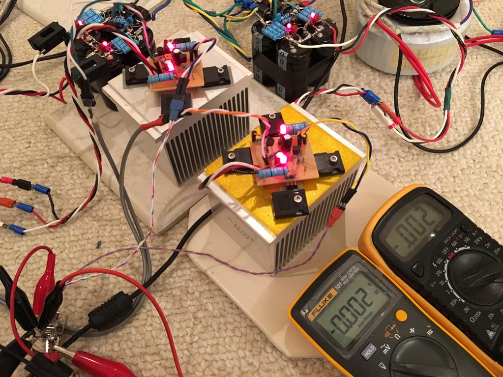
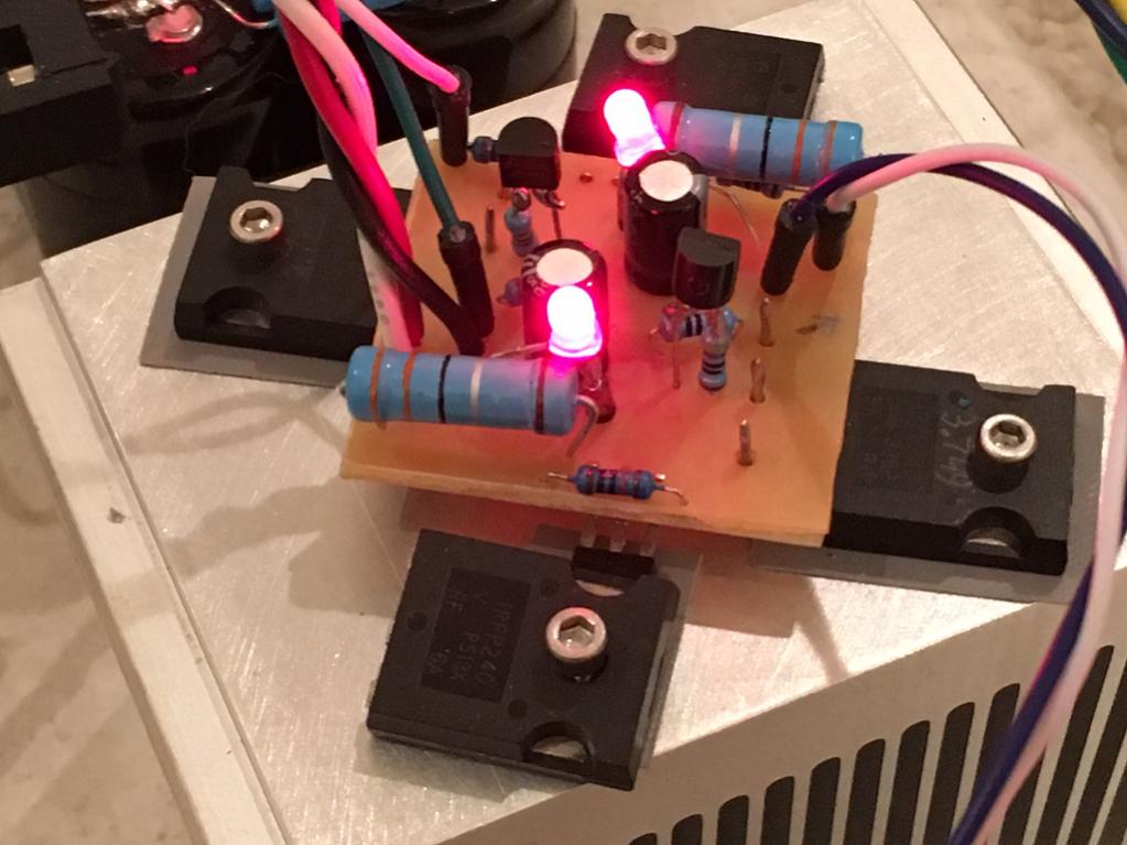
Here is a closeup of the second channel with proper etched PCB (both channels now using PDF iron on transfer PCB's):
Here are the stereo amps showing 2mV offset:
Here is a closeup of the second channel with proper etched PCB (both channels now using PDF iron on transfer PCB's):
Attachments
I would not trust the last digit for a measurement.
Often the spec sheet shows ±tolerance + digits
A reading of 0.002Vdc with a ±0.5%+3digits tolerance could be anywhere from -1.01mVdc to +5.01mVdc
You should switch to the scale that has 0.1mVdc resolution to be more sure of what the offset (or any low voltage) is likely to be.
Often the spec sheet shows ±tolerance + digits
A reading of 0.002Vdc with a ±0.5%+3digits tolerance could be anywhere from -1.01mVdc to +5.01mVdc
You should switch to the scale that has 0.1mVdc resolution to be more sure of what the offset (or any low voltage) is likely to be.
That gives much more confidence. Adding or subtracting 3 least significant digits to those readings leaves one between 1.0mVdc to 1.6mVdc and the other becomes 1.2mVdc to 1.8mVdcIn actual mV mode it shows between 1.3mV to 1.5mV.
All the range of possible voltages are in the same millivolt !
compared to
from -1.01mVdc to +5.01mVdc
That gives much more confidence. Adding or subtracting 3 least significant digits to those readings leaves one between 1.0mVdc to 1.6mVdc and the other becomes 1.2mVdc to 1.8mVdc
All the range of possible voltages are in the same millivolt !
compared to
I was listening to it for 2 hours yesterday running with small fan on heatsink and with DVM hooked up the whole time and DC offset has further stabilized to 0.1mV to 0.3mV the whole time. Amazing stability actually. I am really liking this amp but now wondering if I need something like a simple Juma +6dB preamp using 2sk170 and 2sj74 to provide the gain needed to drive high impedance
phones.
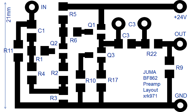
Juma uses this for driving his F5 (says make R6=R1=1k for 6dB gain):
PCB:
Last edited:
I'd use this (post #346) :
http://www.diyaudio.com/forums/pass-labs/146310-bf862-preamp-7.html#post4426944
http://www.diyaudio.com/forums/pass-labs/146310-bf862-preamp-7.html#post4426944
I'd use this (post #346) :
http://www.diyaudio.com/forums/pass-labs/146310-bf862-preamp-7.html#post4426944
Thank you Juma! Another simple gem of a circuit.
It so happens a package of 40 BF862's just arrived the other day.
")
Sort of unrelated but related to all your schematics is how clean and easy to read they are - some of the best drawing on this site IMO. What software do you use to create these nice diagrams? They look like ASCII character based.
Last edited:

- Status
- This old topic is closed. If you want to reopen this topic, contact a moderator using the "Report Post" button.
- Home
- Amplifiers
- Headphone Systems
- MOSFET follower headphone amplifier