I've been using it only in the digital domain so far and am not sure unfortunately, as I don't have any other gear with the balanced, XLR analog or 1/4" connections to test..I was going to start by removing the muting transistors but I cannot find them on the DEQ2496.
The internal power/data cables are not of the ribbon-type as I was hoping. I was going to try and clean the contacts with rubbing alcohol hoping that some contacts on the connectors had just become oxidized and were making a bad, intermittent connection somewhere. I do have some DeOxit Gold, maybe I can treat the pins on the connectors and cables to see if that helps? Besides the DeOxit, I'm not sure what else I can try to restore the pink noise generator functionality..
The internal power/data cables are not of the ribbon-type as I was hoping. I was going to try and clean the contacts with rubbing alcohol hoping that some contacts on the connectors had just become oxidized and were making a bad, intermittent connection somewhere. I do have some DeOxit Gold, maybe I can treat the pins on the connectors and cables to see if that helps? Besides the DeOxit, I'm not sure what else I can try to restore the pink noise generator functionality..
Hello,
I know this thread is old but
does anyone know if in the original DEQ2496 PSU the regulators have the little condensers which are necessary for stability as described in the datasheet? It is 0,1 and 0,33 mfd as a minimum.
Very often in hifi-gear I found regulators without these capacitors and adding some improved the sound clearly audible. (Better Transient response and maybe some db better ripple rejection).
I did not read all the 24 pages, is there a schematic of the original psu?
Bye, Dragan
Ah, thank you a lot!
As I can see the 7815 and 7915 regulators have only Electrolytics of 470mfd on the input and 10 mfd on the output. The output has some 100nano, ok.
So it is probable that a small foil type or kerko on the input (and output) could come closer to what is written in the datasheet on these types of regulators for bettering ripple and transient response. Electrolytics are not good enough for this job.
Usually I add 1mfd foil type condenser directly between the legs of the regulators and very often this makes the sound better as the regulators work better.
I will try this out as this modification is easy to make.
Does it make sense to add some ferrite to the band of wires leading from the smps psu to the digital board?
As I can see c9 and c13 do some rf filtering. Changing this type of x2 condenser against a larger one could help to do this job better.
Bye, Dragan
Last edited:
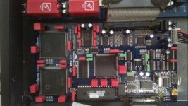
Hi, i want app this mod, look a photo:

Is there a complete list of values and types of caps to mount? I ask why I see them in various sizes.
Why weren't these types of red caps mounted in the upper right area, I presume wima? Is the image complete then when the work is finished?
I hope for an answer.
Thanks
Is there a complete list of values and types of caps to mount? I ask why I see them in various sizes.
Why weren't these types of red caps mounted in the upper right area, I presume wima? Is the image complete then when the work is finished?
I hope for an answer.
Thanks
I just ordered another DEQ2496 because I couldn't get the RTA working on the first one. When it arrives I will be replacing all the electrolytics again and will look to see what smaller value caps have been replaced with those red wimas in the photo. They could be mks, mkp, or even mkc. The green ones may likelier be mks polyester but I cannot be certain. The reason that the electrolytics on the upper right haven't been replaced with films is because they are all likely larger than 0.47uf which is the (general) cut-off from going from the larger potted film types to the smaller electrolytic cans.
When I said "top right" I wasn't referring to electrolytics but to SMDs.
Specifically those close to the AK4393, AK4524 and AK4114 (C21, 32, 22, 23, 24, 34, 18, 19, 20, 30, 14, 16)
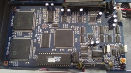
Below is the photo of my pcb which is best seen.
I want to start with mod from the digital pcb as, for the rest, I still have to decide how and what to do. There are various options ... transformers ... opamp..etc

image for

In my image you will find two caps circled in yellow which are absolutely to be replaced as, being of poor quality (like all the others) they introduce noise. In this 3d you can read about it (post #4):
Another (ultimate?) Behringer mod - what can $50 do to DEQ2496 (PART 1)
")
Specifically those close to the AK4393, AK4524 and AK4114 (C21, 32, 22, 23, 24, 34, 18, 19, 20, 30, 14, 16)
Below is the photo of my pcb which is best seen.
I want to start with mod from the digital pcb as, for the rest, I still have to decide how and what to do. There are various options ... transformers ... opamp..etc
image for
In my image you will find two caps circled in yellow which are absolutely to be replaced as, being of poor quality (like all the others) they introduce noise. In this 3d you can read about it (post #4):
Another (ultimate?) Behringer mod - what can $50 do to DEQ2496 (PART 1)
Last edited:
You may enjoy dealing with SMD. I find it overly tedious. The overuse of these ceramic SMD caps used everywhere in this device is.. unfortunate. I want to upgrade the analog out section but am just going to purchase one of those upgrade kits from behringermods if he still sells them.
https://www.behringermods.com/deq2496.html
If it were me dealing with those annoyingly small SMDs, I'd probably also be soldering some potted films with legs directly to the top of the board. Why not just measure their capacitance or use a magnifying glass to see what values are printed on them so you'll know what sizes you'll need?
That PCB you linked, 6 months ago, they were still selling them. I wrote to him.
Unfortunately, the values are not written on the caps and I tried to measure them when mounted but without success. Obvius.
I hate SMD!
I want to buy the material I need first, then I take off the SMD caps, throw them out the window, and vertically attach the replacement caps.
Unfortunately, the values are not written on the caps and I tried to measure them when mounted but without success. Obvius.
I hate SMD!
I want to buy the material I need first, then I take off the SMD caps, throw them out the window, and vertically attach the replacement caps.
I see what you mean. Thanks for sharing that mod link. I forgot about it and had to re-read it to familarize myself, as this thread hasn't been bumped in a while. For starters, looks like you'll need lots of low noise/ low esr electrolytics. Do that before tackling the tiny ceramics (if you haven't done so already) The electros immediately next to ICs would benefit from being OSCONs. The other electros not directly feeding an IC can be bi-polars UES (Muse) and Elna CE.
UHE, FM, UPW are "clean" energetic, perhaps sterile sounding with higher ripple and less ESR in applications where that matters- more similar (perhaps) to an OSCON sound signature which I'm guessing should be more stable and also very clean sounding. An alternative to OSCON for feeding ICs could also be UKL low leakage. Elna RFS Silmic II sound more natural for direct, signal path along with audio bi-polars which can always be used to replace polarized at any time. Check out the Elna CE. They're also bi-polar "audio" caps, but much smaller and easier to place than UES Muse. Hard to find though.
The rest is just a mess of tiny SMD ceramic caps that have to be painstakingly dealt with. You have to de-solder them and remove them from the circuit in order to measure their capacitance. I wonder if they all share the same voltage rating, and if so, what would that be?
For films, I would opt for mkp, mkc, or even pps like the author of the $50 mod thread. These behringers are all a ticking time bomb if you don't at least pre-emptively replace the electrolytics on them before something fails or gets "taken out" by them. Everyone who owns a DEQ2496 should be doing this or face certain catastrophe at their own peril.
The Chinese electrolytics and ceramic SMDs are what holds the unit back from staying more durable and functional over the course of several years as well as fulfilling its inherent design potential. The provided passive components are not to be trusted on this thing (like Cambridge Audio) and should not be overlooked or ignored.
It would've been nice if the person who made the $50 mod thread had taken more close-up photos of his finished work along with all values and locations of all the SMD ceramics he replaced.
Last edited:
I started drawing a map of the ceramic caps.
I have no experience, I am a beginner with datasheets under my eyes and .... guesses.
Besides, English is not my language!
I hope my deq continues to work when I reassemble the card. I don't know if touching all the pins with the tester is good for the dsp ... etc ..
Below what I've done so far:

Link A BIG IMAGE: dav — ImgBB
Where I wrote "TBC" in black or white it means that somehow I have to finish being sure by reading the datasheets better or if someone is an expert .. go ahead!
The caps around the two big dsp should be correct as they are between GND and the various VDD pins of the dsp..which I assume are the power supply pins.
The caps around ak5393 I deduced from the respective datasheet and from some images on the net of a card of a different version than my deq ... which reported the values written on the card.
I reasoned and compared with the datasheet and other information on the net .. and they are certainly fine.
C55 and c44, near the sdram, are between 3.3vdc and GND.
I assume they are 100nF too and have something to do with the ram power supply.
I haven't read the ram datasheet, so I wrote "TBC".
Regarding the DSP in the center of the card:
c67, 39, 54, 47, reading the datasheet, are external capacitors and are between GND and 4 pins of the chip called "VDDINT" (Core Power Supply). It seems that the chip has an internal regulator and that it needs these caps externally.
Given the presumed purpose of the cap .. it is always about power supply ... I assume they are 100nF too.
Wanted dsp chip expert !!!! Help!
I have no experience, I am a beginner with datasheets under my eyes and .... guesses.
Besides, English is not my language!
I hope my deq continues to work when I reassemble the card. I don't know if touching all the pins with the tester is good for the dsp ... etc ..
Below what I've done so far:
Link A BIG IMAGE: dav — ImgBB
Where I wrote "TBC" in black or white it means that somehow I have to finish being sure by reading the datasheets better or if someone is an expert .. go ahead!
The caps around the two big dsp should be correct as they are between GND and the various VDD pins of the dsp..which I assume are the power supply pins.
The caps around ak5393 I deduced from the respective datasheet and from some images on the net of a card of a different version than my deq ... which reported the values written on the card.
I reasoned and compared with the datasheet and other information on the net .. and they are certainly fine.
C55 and c44, near the sdram, are between 3.3vdc and GND.
I assume they are 100nF too and have something to do with the ram power supply.
I haven't read the ram datasheet, so I wrote "TBC".
Regarding the DSP in the center of the card:
c67, 39, 54, 47, reading the datasheet, are external capacitors and are between GND and 4 pins of the chip called "VDDINT" (Core Power Supply). It seems that the chip has an internal regulator and that it needs these caps externally.
Given the presumed purpose of the cap .. it is always about power supply ... I assume they are 100nF too.
Wanted dsp chip expert !!!! Help!
Last edited:
.....Always around the chip in the center of the board .... c43, 66, 68 and 42 are between GND and the power supply pins (3.3vdc) of the chip and, reasoning as for the two largest dsp, they will certainly be 100nF too.
As soon as I can, I'll go ahead and see if I understand what the other remaining ones are!
PS: TBC = to be confirmed (obvius!)
I'm done for today. It's 6:08 AM I'm going to sleep !!!
As soon as I can, I'll go ahead and see if I understand what the other remaining ones are!
PS: TBC = to be confirmed (obvius!)
I'm done for today. It's 6:08 AM I'm going to sleep !!!
Last edited:
....
here in my part it is difficult to find obscons of the right size and specifications.
I found some Panasonic OS-CON 35SEPF22M Polymer Aluminum Solid Capacitor. 22uF, 35V. Size (DxL): 6,3x6mm. Lead spacing: 2,5mm. Low ESR, long life, perfect for low noise audio applications. Low ESR, long life, perfect for low noise audio applications.
22uf could they give problems? too much capacity? anyone knows?
thanks
....
here in my part it is difficult to find obscons of the right size and specifications.
I found some Panasonic OS-CON 35SEPF22M Polymer Aluminum Solid Capacitor. 22uF, 35V. Size (DxL): 6,3x6mm. Lead spacing: 2,5mm. Low ESR, long life, perfect for low noise audio applications. Low ESR, long life, perfect for low noise audio applications.
22uf could they give problems? too much capacity? anyone knows?
thanks
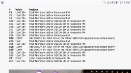
You don't want to chance capacitance on your replacements unless its been recommended. I still haven't received my DEQ to verify, as I know there are also larger capacitance power filter electrolytics inside, but for starters, here are two photos which show you what you're working with.
It looks like you'll need 10-20 low noise 10uf 25V caps. Oscons are good, but UHD, UHE, UPW, FM or UKL can also work here. UKL is the low-leakage type, the others are more low ESR. Both types are good for feeding ICs, but not direct audio signal path, in my opinion.
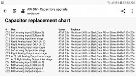
Also, looks like 20 or so 47uf 25V for the analog circuit. This is where you'd want to purchase more audio sounding types. RFS Silmic II and UES Muse bi-polar are both very nice, but are twice as large as every other audio series. UFW, UKW, Elna CE-BP, UKA, UKZ are all fine sounding audio electrolytics.
It appears according to the $50 mod link you posted in the cap upgrade section, the person was adding 10V electrolytics on top of the 100nF caps, of which there are many, perhaps dozens on the DEQ. Without knowing more, this tells me that all those 100nF SMDs may only be rated at 10V (or less possibly) if the modder knew what they were doing. This tells me that those 100nF caps could all be replaced by 100nF 10V equivalents possibly. Order some pps or mkp to replace these. I still don't know why he was bypassing some of them with electrolytics instead of just removing them entirely and just installing electrolytics in that particular section of 100nF caps.
Attachments
Last edited:
For the cap on the output card (card with connectors and opamp) .. yes the problem is the space unless instead of putting 47uf you put 22 or 33uf.
Maybe so we could put the silmic or bipolar.
Some considerations and two calculations should be made with the formulas to understand the cutoff frequency.
It then depends on how you use the deq.
If it is used only at home, going out only unbalanced, you could also put 2 nice big mkp caps (mundorf type) connected with wires!
For the moment, as I am mainly and initially dealing with the digital card I am looking at what cap options there are. What you mentioned are on my guess list. There are also the panasonic FRs which boast super ultra-low esr almost on par with the oscons. Then there are alternatives to oscon (always polymers) from other brands such as kemet..etc..same specifications.
Even if I haven't finished "mapping" the caps of the (digital) card yet, today I reassembled the deq ... connected ... and to my amazement it still works perfectly !! yuhhuuu !!
Yesterday I poked him everywhere for hours .. with the multimeter! hahah
Tomorrow or the day after tomorrow I take the card off the deq again and try to go ahead and finish figuring out the capacitors.
The voltage values of all the tiny ceramics are low, they work on 3.3v or on 5v.
10v to mount are also enough.
Today with the deq access and sounding I checked with the multimeter what voltages were in all the remaining ceramics.
Useful clues to understand, together with the datasheets, what function the caps perform!
Thanks for the 2 images, I already knew that site where you got them from! they are part of the documents that will help us to make the super recap.
Good night!
PS1: Interesting link for the power supply (same as dcx): The BEHRINGER DCX2496 Power Supply | Blog di Mauro Munzi
PS2: Direct and passive output from the dac to the output connectors, without opamp and without transformers. Only good cap. Interesting!
You can download it here from my google drive: DEQ2496 and DCX Uscita diretta Passiva (Only Cap).pdf - Google Drive
today notes
Last edited:
Mine flashes at me on power up. Speculation why?
Merry Christmas 🎁
I think I have read everything that exists on the internet of the deq. It could be a false contact in the psu to digital board connector. as they have already advised you!
merry christmas!


- Home
- Source & Line
- Digital Line Level
- Modify behringer DEQ2496?