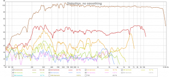
Pulled the mids - noticed my t-nuts were just a touch over flush with the driver mounting plate still. Changed to some new mids as well. I don't like making multiple changes like that but it's a pain taking the wg off it's mount to pull the drivers off. No change in the distortion. I have some small foam plugs cut that fit the mid ports which helps a tiny bit with hf diffraction off the ports. Pulled those out and things are much better. One (or more!) of the plugs must have been out of whack and touched the cone. The distortion still isn't on par with the 1 port/driver version but much better. I'll bring my precision square home from work this week and see how flat my mounting plates are.
Attachments
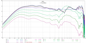
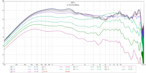
Here's the polars for the 1 mid port/driver and 2 ports/mid driver. This is a BMS 4552nd and two Celestion TF0401MR mids. The main thing I'm looking for is hf diffraction from the mid ports, and I wanted to see the effect of 1 vs 2 ports. When I originally did the testing in this thread my mid ports were too small. I didn't see anything in the data to suggest that but HornResp sims and work others have done convinced me of that....and I wanted to try to get the mids to play higher.
You'll also notice that I'm only using 2 mids per horn rather than the 3 I tested. When I set out to build these I intended to use 3, but two are much easier to get onto the horn and will offer plenty of output. These are eq'd to about +/- .5dB at 20° with a bit of down tilt. I'd say having 2 smaller ports per driver is much better in terms of hf diffraction, and I'll go ahead and redo the ports on the 1 port/mid horn to match the 2 port horn.
In the end these "mini Synergy's" will sit over a couple of sealed TD15M woofers to be configured horizontally or vertically - whatever gives the best in room response. XO to the woofers will be around 300hz.
Attachments

Kind of weird how the treble peaks up there above 5kHz off-axis. Are you sure the Celestion output isn't getting into the combined response up there, or is that just from diffraction? Seems pretty severe.
On my newest waveguide, I was surprised to see very little effect from the midrange holes, but quite a bit from woofer holes that were further out (better now that I moved them further). That's with a 90x65 essentially conical (with OS throat) waveguide.
On my newest waveguide, I was surprised to see very little effect from the midrange holes, but quite a bit from woofer holes that were further out (better now that I moved them further). That's with a 90x65 essentially conical (with OS throat) waveguide.
Can it look like all the other axis except the DSP EQed 20º one have some more or less uniformity to each others and if that is right it sounds logic its better base DSP EQ to one of the others so all those get uniform smooth and then only 20º axis stand out little unsmooth, its little hard really to see lines because of same colors but it looks that even the curves within 5º of the DSPed axis is not very same and leads to think can it be smoothing or gating window that DSP correction is based on is by accident not real minimum phase so that ruins all the other axis after the correction.
Last edited:
Nate for EQ, let me recommend this: download the Omnimic software (I wrote it, but the program is free and works for response averaging). Then on the top left, get the "File" menu and then the "make Weighted Average" menu. Then just load up all your response files in the form that pops up (I weight the on-axis half as much as the others). Your weighted average curve appears on the plot (might have to move the ref scale up or down to see it). Do your EQ to that, which will flatten power response. Or you can use different weighting to go somewhere between power response and your chosen axis response.
If you use PEQ to equalize, you can even use the equalizer function in Omnimic to figure the values. Go to the "Main Curve Math" menu at top of screen, and choose "show equalizer" and put a check in the box "show parametic EQ filters". You can play with them yourself to flatten or use the app to figure them out for you (click "Auto" and you get buttons for that).
If you use PEQ to equalize, you can even use the equalizer function in Omnimic to figure the values. Go to the "Main Curve Math" menu at top of screen, and choose "show equalizer" and put a check in the box "show parametic EQ filters". You can play with them yourself to flatten or use the app to figure them out for you (click "Auto" and you get buttons for that).
What's weirdest is how at ~7kHz and 30degrees off-axis it gets about 7dB stronger (relative to 2kHz) than it was when directly on-axis. And about 3dB stronger, without comparsion to other frequencies, at 7kHz than on-axis. Can't see how that happens!
Where are the holes relative to the axes? Isn't that a round horn? Then rotate it and place the anomaly where it does the least harm - up in the air or down on the floor rather than off on the side
Is the effect greater because there are no corners in which the holes can be hidden?
I want to point out that I'm not intending to use them this way, I chose 20° because that is typically my design axis due to the way I toe my speakers....old habit. I eq'd as flat as possible so the different port versions could be compared equally. In practice I find that eq'ing these waveguides based on an avg of measurements out to 40° and a few vertically to work the best. Pretty sure I have the OmniMic sw Bill I will check it out.
nc535 - the wg is elliptical - 90x60 with an 18" wide mouth. I think more details on the wg are in the first post of this thread. The pics from post #412 show the 2 different port configurations. Port locations were in fact chosen where I thought they would do the least harm.
nc535 - the wg is elliptical - 90x60 with an 18" wide mouth. I think more details on the wg are in the first post of this thread. The pics from post #412 show the 2 different port configurations. Port locations were in fact chosen where I thought they would do the least harm.
nc535 - the wg is elliptical - 90x60 with an 18" wide mouth
Very similar to what I made, really.
In (a grand total of) one test, I tried moving ports into corners vs moving them further out where they'd be clustered closer to each other and found that the closest distance to each other worked best. But that might've just been that one horn. I do know that having the ports too far from each other can cause bad pattern problems, but that's more in the midrange. This effect seems to be about 7kHz, quarter wave about 2", half wave about 4", if that's relevant to the issue. It's still really odd how extra off-axis energy seems to get generated, or is it that there's somehow a suckout near on-axis at 7kHz?
It's still really odd how extra off-axis energy seems to get generated, or is it that there's somehow a suckout near on-axis at 7kHz?
I think that's what it is. I thought it seemed that the un-eq'd axial curve was a bit weak in that region compared to what I'm used to seeing with this wg without the mid ports. Unfortunately I didn't save the raw response. Next time I'm setup for measurements I'll compare to my older data.
One thing I might try is to use two smaller ports on one mid and a larger port on the other in an attempt to randomize the effect of the ports.
Geddes' round waveguides have a suckout directly on-axis, which he explains by reflection from the mouth. It seems that the more symmetric the waveguide is, the more geometric effects will affect what happens on-axis (because all the effects reinforce each other when seen from there). Maybe your randomizing might be the way to go. The ellipse would be closer to a circular horn than something with a less regular mouth.
I've wondered whether there might be some merit in making waveguides very asymmetric (like a quadrilateral with no parallel sides or something like that). Though maybe worrying about on-axis oddities isn't a big deal, since it makes up a small portion of the power response and there are other benefits to not listening to waveguides directly on-axis anyway.
I've wondered whether there might be some merit in making waveguides very asymmetric (like a quadrilateral with no parallel sides or something like that). Though maybe worrying about on-axis oddities isn't a big deal, since it makes up a small portion of the power response and there are other benefits to not listening to waveguides directly on-axis anyway.
Good point about the axis suckout. Filling and drilling holes is easy enough I think I'll try my idea.
I've been thinking the same thing lately about an asymmetric wg, but I think the SEOS shape gets close enough from what I've seen. Certainly your 3d print results are awesome!
I've been thinking the same thing lately about an asymmetric wg, but I think the SEOS shape gets close enough from what I've seen. Certainly your 3d print results are awesome!
I have a hard enough time with square ish cuts much less anything asymmetric!
Just mess up trying to make them squarish then, and they should come out asymmetric
")
Geddes' round waveguides have a suckout directly on-axis, which he explains by reflection from the mouth. It seems that the more symmetric the waveguide is, the more geometric effects will affect what happens on-axis (because all the effects reinforce each other when seen from there). Maybe your randomizing might be the way to go. The ellipse would be closer to a circular horn than something with a less regular mouth.
I've wondered whether there might be some merit in making waveguides very asymmetric (like a quadrilateral with no parallel sides or something like that). Though maybe worrying about on-axis oddities isn't a big deal, since it makes up a small portion of the power response and there are other benefits to not listening to waveguides directly on-axis anyway.
The axial hole is not a "reflection" as you suggest I said, but a diffraction off of the mouth edge. There is a small component of reflection generated standing wave across the waveguide at the mouth, but this is the lessor effect. In the larger 18" waveguide with very large mouth radi, it is mostly gone. The 15" (Abbey) was worst case, with the 12" (Nathan) next.
While I mostly don't see this hole as a problem, I have tried things to alleviate it in the Abbey. I made the mouth square(ish) from an axisymmetric waveguide throat. The axial hole was much better, but other issue crept in that the round mouth did not have. All-in-all I am not sure that it was an improvement or not. I never built more than one.
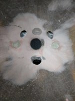
Back at work. Got the old ports filled and new ones drilled. The top mid has two roughly .5" ports and the bottom has single .75" or so dia port. I forget the drill sizes but I tried to make the area of the two ports = to the area of the single port.
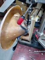
I got smart this time and made a drilling fixture that mounts to the cd mount holes, so the ports are drilled at an angle to the horn wall. A 5/16 flat end mill made starting the holes on angle a breeze and I finished with the correct drill size. The ports are much cleaner and consistent doing it this way. In the pic you can see plumbers putty covering holes left and right of the cd entrance. I'm now screwing the compression driver onto the wg through the inside of the wg itself. This had to be done due to the way the mids mount and it's much easier getting the cd lined up with the wg entrance this way.
I got smart this time and made a drilling fixture that mounts to the cd mount holes, so the ports are drilled at an angle to the horn wall. A 5/16 flat end mill made starting the holes on angle a breeze and I finished with the correct drill size. The ports are much cleaner and consistent doing it this way. In the pic you can see plumbers putty covering holes left and right of the cd entrance. I'm now screwing the compression driver onto the wg through the inside of the wg itself. This had to be done due to the way the mids mount and it's much easier getting the cd lined up with the wg entrance this way.
Attachments
- Status
- This old topic is closed. If you want to reopen this topic, contact a moderator using the "Report Post" button.
- Home
- Loudspeakers
- Multi-Way
- Mini-Synergy Horn Experiment