No, derived phase is a phase response calculated from the dB response curve using a "Hilbert Transform", which will be correct if what you measure is a minimum phase device AND you calculate using correct, but usually largely guessed, response rolloffs in the frequencies well outside its passband (and usually outside of what your mic and system can measure). Some advise doing that, but I don't usually (why calculate what can at best be a good approximation if you already have actual, measured phase?).
The third "together" measurement is so you can simulate that condition in your modeler (PCD or XSim). You adjust the relative delay difference between the drivers in your sim until the dB curve result matches, then use that delay difference in your to sim wben doing your actual crossover.
The third "together" measurement is so you can simulate that condition in your modeler (PCD or XSim). You adjust the relative delay difference between the drivers in your sim until the dB curve result matches, then use that delay difference in your to sim wben doing your actual crossover.
That isnt too bad if your amp can handle the 3 ohm loads and if your tweeter can handle LFs all the way down to DC (which that network won't block)! Its always a good idea to look at the electrical response INTO the drivers, particularly tweeters. Just because nothing comes out of the tweeter at LF doesnt mean the tweet will be happy about having it applied...
Another thing you may want to do is adjust overall delay in your sim from the power amp/generator to maximally straighten out the phase curve dis0lay at HF. Its a lot easier then to tweak the network for phase nearest 0degrees than to just eyeball an impulse or squarewave response for what looks like it might be the best shape. Then you get a number "within 20 degrees" or whatever.
Last edited:
Ok thanks Bill I'll look into it.
I meant to say hundredths....J River's dsp has tenth increments.
Yeah. There's a bit of drift but it's like tenths of a ms if I'm quick about it.
I meant to say hundredths....J River's dsp has tenth increments.
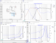
Here's another go. I thought it was pretty cool (on the one that I posted last night) that I could tweak the 1st order hpf cap with a resistor across. Never bothered to look at voltage as bwaslo pointed out. No free lunch as usual. How's this? Is the massive impedance peak at 4khz anything to worry about? I put in a compensation circuit before the hpf but it had no effect on the transfer function....only the impedance so I took it out.
Attachments
Here's another go. I thought it was pretty cool (on the one that I posted last night) that I could tweak the 1st order hpf cap with a resistor across. Never bothered to look at voltage as bwaslo pointed out. No free lunch as usual. How's this? Is the massive impedance peak at 4khz anything to worry about? I put in a compensation circuit before the hpf but it had no effect on the transfer function....only the impedance so I took it out.
That's a pretty nice result for passives and your first attempt (quite a simple xo as parts counts go). Your mini synergy horn has the capability to be transient perfect and minimum flat phase if you put the ports at the right place and tweak the XO like Bwaslo did on his Cosyne.
I admit, playing around with XO sims can be kind of addictive. It's like a video game - trying to eek out the highest score with the flattest response and lowest parts count
")

Response looks nice.Here's another go. I thought it was pretty cool (on the one that I posted last night) that I could tweak the 1st order hpf cap with a resistor across. Never bothered to look at voltage as bwaslo pointed out. No free lunch as usual. How's this? Is the massive impedance peak at 4khz anything to worry about? I put in a compensation circuit before the hpf but it had no effect on the transfer function....only the impedance so I took it out.
Regarding LCR or RC networks the theory i seen is they shall be mounted at driver and reason is then XO parts looks into a linear impedance making calculation for XO parts value throw the right targeted slope, but they also in theory make a electric dampening point for the motor if mounted at driver.
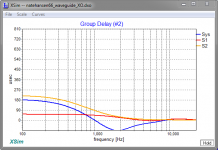
Could be wrong worry about this but if fire your schematic into textbook linear 8 ohm driver to model your tweeter and textbook linear 2,66 ohm driver to model your injection ports get below group delays, yellow is injection ports red is tweeter and blue is system. Know scale is uS but at higher frq they mean something relative to periodT, so if target is for waveguide as to work as a perfect optimated point source think would investigate if any strange wrigles turn up in live measurements at uS scale under group delay.
Attachments
Last edited:

So after a long audio hiatus I'm back and up to Synergy business. Finally got to converting the waveguides from my main system to 2-way synergy horns. Pretty much borrowed the conversion process right from bwaslo's "Small Syns"playbook. Thanks Bill!
Been listening to one in mono for a couple weeks and I'm excited to get a stereo pair rolling. After getting one done I decided I wasn't done testing mid port configurations so I drilled the ports on second wg differently. Hopefully I'll get set up for measurements and have data to post this weekend. Here's a teaser for now:

Been listening to one in mono for a couple weeks and I'm excited to get a stereo pair rolling. After getting one done I decided I wasn't done testing mid port configurations so I drilled the ports on second wg differently. Hopefully I'll get set up for measurements and have data to post this weekend. Here's a teaser for now:
I've been getting data the last couple days, comparing 2 ports per driver vs 1 large port. There are two 4" closed back mids per horn. I'll attach pics of the ports......the velcro on the wg holds foam plugs in place. The port center of the two port/driver version is 1.4" from the CD throat and the one port/driver version is 1.5" from the throat. I tried to make the area of the 2 ports/driver version equal to the area of the single port but it is slightly larger for the 2 port version.
I have detailed polars of both but I'm seeing some issues with mid distortion on the 2 port version that I can't reconcile. I'll post that data next when I get back on my PC.


I have detailed polars of both but I'm seeing some issues with mid distortion on the 2 port version that I can't reconcile. I'll post that data next when I get back on my PC.
Sorry for the goofy pics.......posted from my phone.
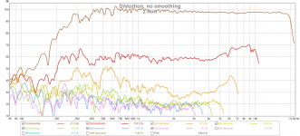
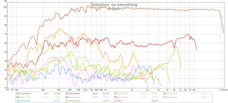
Here is the distortion data take at 42" away from the wg mouth at about 100dB. These were taken back to back. I'm not sure what to make of the distortion on the mid in the 4 port version. I noticed that yesterday when I was getting the polar data. I removed the mids and noticed the t-nuts that I was using to mount the drivers were sticking up over the mounting plate a bit. I filed those down and made sure the mounting surface was nice and clean. I also added some gasket tape. There is plumbers putty in the mid chamber to take up some volume but that does not protrude above the driver mount plate in any way. I reattached the drivers and took the measurements that you see back to back. I'm not really sure what to make of this........I have more of these mids on hand I'm going to try some different drivers.
Here is the distortion data take at 42" away from the wg mouth at about 100dB. These were taken back to back. I'm not sure what to make of the distortion on the mid in the 4 port version. I noticed that yesterday when I was getting the polar data. I removed the mids and noticed the t-nuts that I was using to mount the drivers were sticking up over the mounting plate a bit. I filed those down and made sure the mounting surface was nice and clean. I also added some gasket tape. There is plumbers putty in the mid chamber to take up some volume but that does not protrude above the driver mount plate in any way. I reattached the drivers and took the measurements that you see back to back. I'm not really sure what to make of this........I have more of these mids on hand I'm going to try some different drivers.
Attachments
Sorry for the goofy pics.......posted from my phone.
Here is the distortion data take at 42" away from the wg mouth at about 100dB. These were taken back to back. I'm not sure what to make of the distortion on the mid in the 4 port version. I noticed that yesterday when I was getting the polar data. I removed the mids and noticed the t-nuts that I was using to mount the drivers were sticking up over the mounting plate a bit. I filed those down and made sure the mounting surface was nice and clean. I also added some gasket tape. There is plumbers putty in the mid chamber to take up some volume but that does not protrude above the driver mount plate in any way. I reattached the drivers and took the measurements that you see back to back. I'm not really sure what to make of this........I have more of these mids on hand I'm going to try some different drivers.[/QUOTE
How can the mid be flat on to 20 with no sign of breakup? I'd expect breakup here we see the distortion peaks
Sorry for the goofy pics.......posted from my phone.
Here is the distortion data take at 42" away from the wg mouth at about 100dB. These were taken back to back. I'm not sure what to make of the distortion on the mid in the 4 port version. I noticed that yesterday when I was getting the polar data. I removed the mids and noticed the t-nuts that I was using to mount the drivers were sticking up over the mounting plate a bit. I filed those down and made sure the mounting surface was nice and clean. I also added some gasket tape. There is plumbers putty in the mid chamber to take up some volume but that does not protrude above the driver mount plate in any way. I reattached the drivers and took the measurements that you see back to back. I'm not really sure what to make of this........I have more of these mids on hand I'm going to try some different drivers.
How on earth did you get the response of the BMS so flat?
That's way better than the Danley speakers.
nc535 - yes that's the system response with the cd. The goofy distortion on the 4 port version is isolated to the mid driver.
PB........dsp! Once I post the polars you will see the complete picture of course. Just trying to hammer out this distortion issue as I get the best overall response with the 4 port version. I should add that this measurement was taken at 20° which was my design axis. I tried to make this angle flat on both version to make everything the same. Basically normalizing to 20°.
PB........dsp! Once I post the polars you will see the complete picture of course. Just trying to hammer out this distortion issue as I get the best overall response with the 4 port version. I should add that this measurement was taken at 20° which was my design axis. I tried to make this angle flat on both version to make everything the same. Basically normalizing to 20°.
Bill Waslo, do you hammer the response flat like Nate did? Your Synergy Horns are noticeably smoother in the treble than the SH-50. I wonder if that 'smoothness' can be achieved with just DSP.
For the plots I publish I don't. I listen either way, depending on what I've been doing with it. I don't notice much difference in quality between EQd or not EQd (eyes don't see graphs the same as ears hear sound!). I think when you listened to mine, the upstairs ones (sealed SmallSyns) had eq (otherwise they wouldn't have much bass), the CoSynes or ported SmallSyns probably didn't. I haven't tried EQ on the new (yet to be named) 3D printed horns.
Nate -- on the midrange distortion: Be really careful to make sure that the surface the midranges get bolted to is very flat. It doesn't take much warp to make the voice coils rub and the cone surrounds to get jacked out of shape. I had a bad distortion problem on my recent horns (audible, didn't even need to measure it), was from a bump on the seam where the mids sit.
Nate -- on the midrange distortion: Be really careful to make sure that the surface the midranges get bolted to is very flat. It doesn't take much warp to make the voice coils rub and the cone surrounds to get jacked out of shape. I had a bad distortion problem on my recent horns (audible, didn't even need to measure it), was from a bump on the seam where the mids sit.
I'm about to pull the mids right now......I'll take a look thanks.
Patrick - once I post the polars of what I'm working on I think you will be less impressed. Anyone can make anything flat at a single point in space
- Status
- This old topic is closed. If you want to reopen this topic, contact a moderator using the "Report Post" button.
- Home
- Loudspeakers
- Multi-Way
- Mini-Synergy Horn Experiment