Oh wow Patrick. That's a gem!
Thanks! I've tried every way to make a waveguide, and 3D printing is by far the most satisfying. It's not the fastest - it takes a while to make a model. But the results are without peer. My fiberglass waveguides always looked a little iffy.
Then again, I've made a couple of fiberglass waveguides that looked good, but it honestly required forty hours to make the mold and the waveguide.
It generally takes me 4-8 hours to make a waveguide in 3D, and about 20 hours to print. (Obviously, the print time doesn't require much of my attention.)
Anybody experienced these Audio Spotlight - Add sound and preserve the quiet. ?
Yes, at trade shows. But I don't see the relevance to this thread.Anybody experienced these Audio Spotlight - Add sound and preserve the quiet. ?
Yes, at trade shows. But I don't see the relevance to this thread.
It seems to have a narrower beam like some of the Synergys, hence just mentioned it here...
It seems to have a narrower beam like some of the Synergys, hence just mentioned it here...
If these are the giant NXT panels, I heard some at a strip club in Utah lol.
Very directional, no bass, no treble. Definitely more pleasant than the average cheap prosound speaker, but not hifi.
I'm not sure what you think is wrong. Are you sure you understand it completely?
There are a lot of "experts" on the forum who demand much more of other members than they are willing to do themselves. All I ask for is fair play. But this is a subject better suited to another thread. Send me a PM if you wish to discuss it further.
There are a lot of "experts" on the forum who demand much more of other members than they are willing to do themselves. All I ask for is fair play. But this is a subject better suited to another thread. Send me a PM if you wish to discuss it further.
Back to the Synergy 
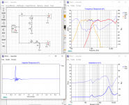
I got the necessary measurements this morning and I've been screwing around in XSim for a couple hours now.....this is my first passive xo. This is how I ended up after tweaking the values to match what PE has in stock. Any further eq can and will be done in DSP - I'm just looking to eliminate an amp channel. Impedance is pretty low due to the parallel wiring on the mids but my amp can handle it. Any thoughts/obvious things that this passive newb can't see?
I got the necessary measurements this morning and I've been screwing around in XSim for a couple hours now.....this is my first passive xo. This is how I ended up after tweaking the values to match what PE has in stock. Any further eq can and will be done in DSP - I'm just looking to eliminate an amp channel. Impedance is pretty low due to the parallel wiring on the mids but my amp can handle it. Any thoughts/obvious things that this passive newb can't see?
Attachments
Back to the Synergy
I got the necessary measurements this morning and I've been screwing around in XSim for a couple hours now.....this is my first passive xo. This is how I ended up after tweaking the values to match what PE has in stock. Any further eq can and will be done in DSP - I'm just looking to eliminate an amp channel. Impedance is pretty low due to the parallel wiring on the mids but my amp can handle it. Any thoughts/obvious things that this passive newb can't see?
I'm not expert but remember when i did a passive two way circuit for xrk971 i copyed same slope curves as he was satisfied with and had dialed in with his miniDSP using only 4 components in XSim based on frd plus zma-files from X's build. Problem was when mounted in US i had not counted for delay he dialed in with miniDSP, and the passive allpass we tried in sim to account for this added phase turn which ruined the BW1 design original was based on. He had to put tweeter in separated enclosure and physical step baffle distance to same as miniDSP data to get that passive XO to work right.
Pretty sure you have dual channel measurement setup that tells real offset timing between drivers and suggest you put those data into the slowest of the drivers S1 or S2. Doubleclick driver that needs delay and in "mod delay" add positive value in inches if that driver is delayed verse the other, and then doubclick "Power amp" and set same value but in advance (minus) to get phase right in frq response window. This offset change will probably change your slopes and need new component values, and know you haven't any delay set right now because then either S1 or S2 is renamed S1m or S2m (mod delay).
Hope I'm on track and info is helpful.
Byrtt has a good point. When I designed my Trynergy DSP XO using PCD, it took into account the physical offset calculated using the optical interference method by predicting the sum parallel response based on measurement of tweeter and woofer only. Setting a physical offset in PCD allowed the predicted sum to match the measured exactly. From that point on, the XO could be designed as if the two drivers were mounted flat on a baffle even though they were already offset in the horn.
Byrtt has been very good at designing XO's in Xsim but crazy thing is he has never actually built one himself. !
Byrtt has been very good at designing XO's in Xsim but crazy thing is he has never actually built one himself. !
Ok yeah I was wondering how I'd account for the delay on the mids. I'll get that dialed in and see how it turns out. Thanks
did you measure using a dual channel setup? if so then the data should have correct relative phase already so no additional delay should be required. You'll basically be creating a filter for that point in space in that situation. Probably worth clarifying what data you're using though. Also do you have a target response in mind?
Thats a good argument for always measuring each pair of drivers' responses three times: each by itsel (including phase of course), and one with both together, so you can always align your simulation with actual time delay relationships. Even if your measurement system is supposed to provide actual time delays, you might be surprised how many soundcards, particularly USB based ones, dont use the same clock for recording and playing (so timing isn't well maintained unless operated in true dual channel, the bypass channel signal being acquired every time).
did you measure using a dual channel setup? if so then the data should have correct relative phase already so no additional delay should be required. You'll basically be creating a filter for that point in space in that situation. Probably worth clarifying what data you're using though. Also do you have a target response in mind?
No dual channel this time, but I did do a combined measurement.......see below. No real target response other than fairly flat. I'll straighten everything out and hit a target with DSP.
Thats a good argument for always measuring each pair of drivers' responses three times: each by itsel (including phase of course), and one with both together, so you can always align your simulation with actual time delay relationships. Even if your measurement system is supposed to provide actual time delays, you might be surprised how many soundcards, particularly USB based ones, dont use the same clock for recording and playing (so timing isn't well maintained unless operated in true dual channel, the bypass channel signal being acquired every time).
Is this what the "derived phase" option is for? I do have a combined measurement but wasn't sure how to use it. I'll admit I didn't look into it too much or look for any kind of guide online. Probably a case of RTFM
That's a good point about the clock issue. My dual channel setup is a bit of a kludge with the output and input being completely different devices. I have good luck getting the relative driver delay with measurements in quick succession. It comes out closer than the finest increment of delay I have in my DSP anyways.
That is lucky. Using separate record and play devices usually just ends up a big mess when I do it.I have good luck getting the relative driver delay with measurements in quick succession. It comes out closer than the finest increment of delay I have in my DSP anyways.
That is lucky. Using separate record and play devices usually just ends up a big mess when I do it.
Yeah. There's a bit of drift but it's like tenths of a ms if I'm quick about it.
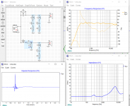
So this passive xo stuff is actually kinda fun. I think I got the combined measurement overlay/delay figured out, and I had to tweak my xo as expected. I don't have a clue yet about series vs shunt notch filters, but the shunt got me where I wanted to be. How's this?
I'm going to get some measurements from my main rig, probably tomorrow, and have a go at a passive xo for that too
Attachments
- Status
- This old topic is closed. If you want to reopen this topic, contact a moderator using the "Report Post" button.
- Home
- Loudspeakers
- Multi-Way
- Mini-Synergy Horn Experiment