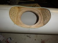
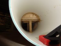
That was the only tricky bit since I didn't want the drivers protruding outside the pipe circumference.
As you can see from the photos, i used a ply mounting plate and HEAPS of liquid nails, the dowels hold the whole deal in place with more liquid nails.
I then shaped the outer surface with Plasti-Bond, a kind of fiberglass/bog stuff.
These are 1200mm long and have a random exit throat size, because I have no idea how to use MJK's worksheets yet and just like building things.
Speaking of which Dave + other!!!
http://www.diyaudio.com/forums/full-range/179311-atl.html#post2401567
Dean
Attachments
How much power in watt needs an amplifier to drive nicely chr70 speakers?
Actually I use them with an amp ta2024 tripath chip, which is too weak (10w real). Do you think a ta2022 or tk2050 (both tripath 100w x2 4ohm) will bee fine?
Someone told me that for a speaker with impedance of 3,60 and efficiency at 84,5 I should use even more power.
Actually I use them with an amp ta2024 tripath chip, which is too weak (10w real). Do you think a ta2022 or tk2050 (both tripath 100w x2 4ohm) will bee fine?
Someone told me that for a speaker with impedance of 3,60 and efficiency at 84,5 I should use even more power.
How much power in watt needs an amplifier to drive nicely chr70 speakers?
Actually I use them with an amp ta2024 tripath chip, which is too weak (10w real). Do you think a ta2022 or tk2050 (both tripath 100w x2 4ohm) will bee fine?
Someone told me that for a speaker with impedance of 3,60 and efficiency at 84,5 I should use even more power.
too many factors to be considered, and there really is no single right answer - 100 "real" watts would be more than enough to hurt your ears and or the drivers
a lot of folks are quite happy with the quality of output from the CHR70 with as little as 10-12w of tube power (as we all know, they're "bigger" watts
 )
)a lot of folks are quite happy with the quality of output from the CHR70 with as little as 10-12w of tube power (as we all know, they're "bigger" watts
Don (aka Doorman) is happy with 3.5.
dave
Don (aka Doorman) is happy with 3.5.
dave
but then he's a half deaf old fart like me who listens to only chicks and guitars and not very loud at that
now it's on ....
where's Cal to tell us how much is not enough?
who's been into the X-mas cheer and confections a bit early? - my head's gonna hurt later this evening
No argument from me, Chris! ( birth certificate says 65 in 2011)but then he's a half deaf old fart like me who listens to only chicks and guitars and not very loud at that
now it's on ....
where's Cal to tell us how much is not enough?
who's been into the X-mas cheer and confections a bit early? - my head's gonna hurt later this evening
The requirements for fullrangers pour moi ,are shrinking all the time- hearing impairment has its advantages
!Best, Don
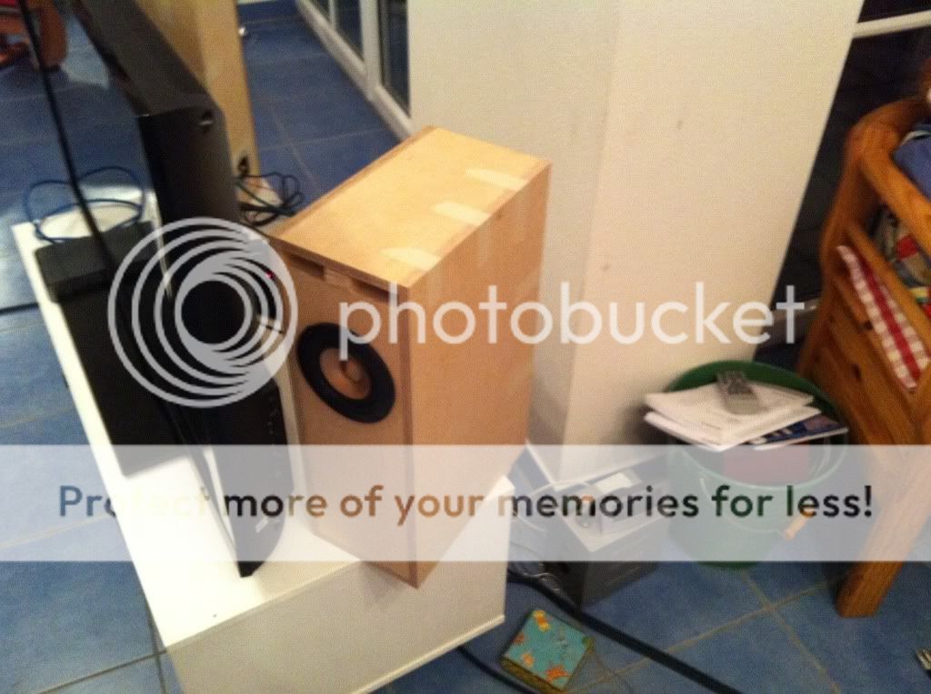
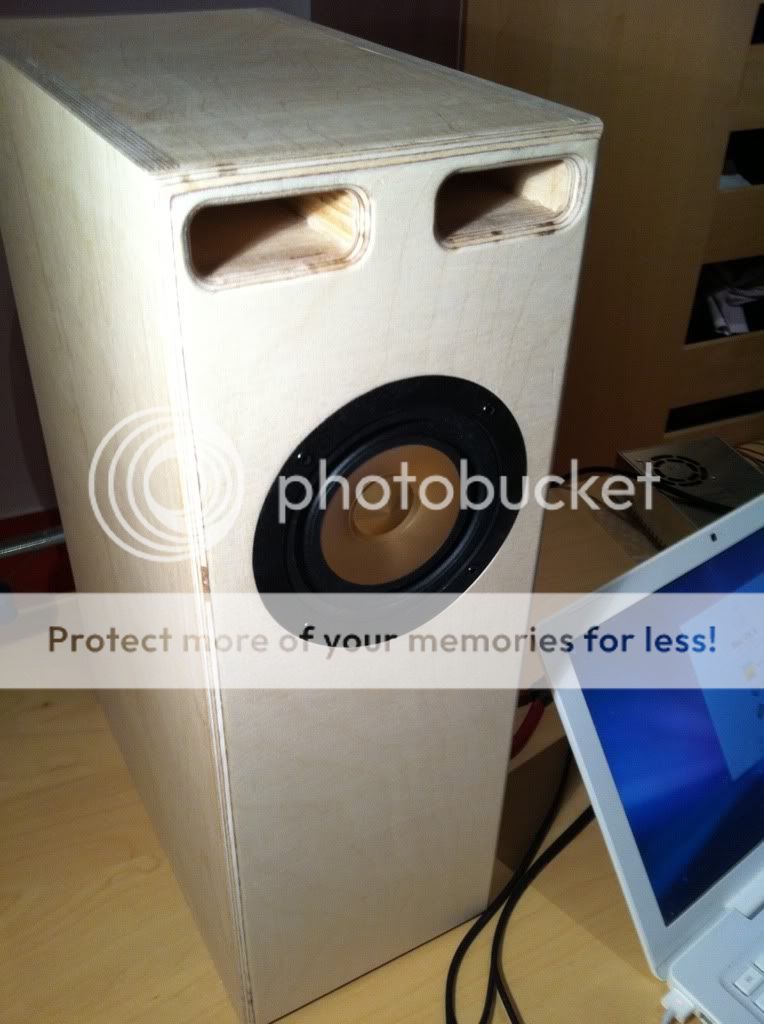
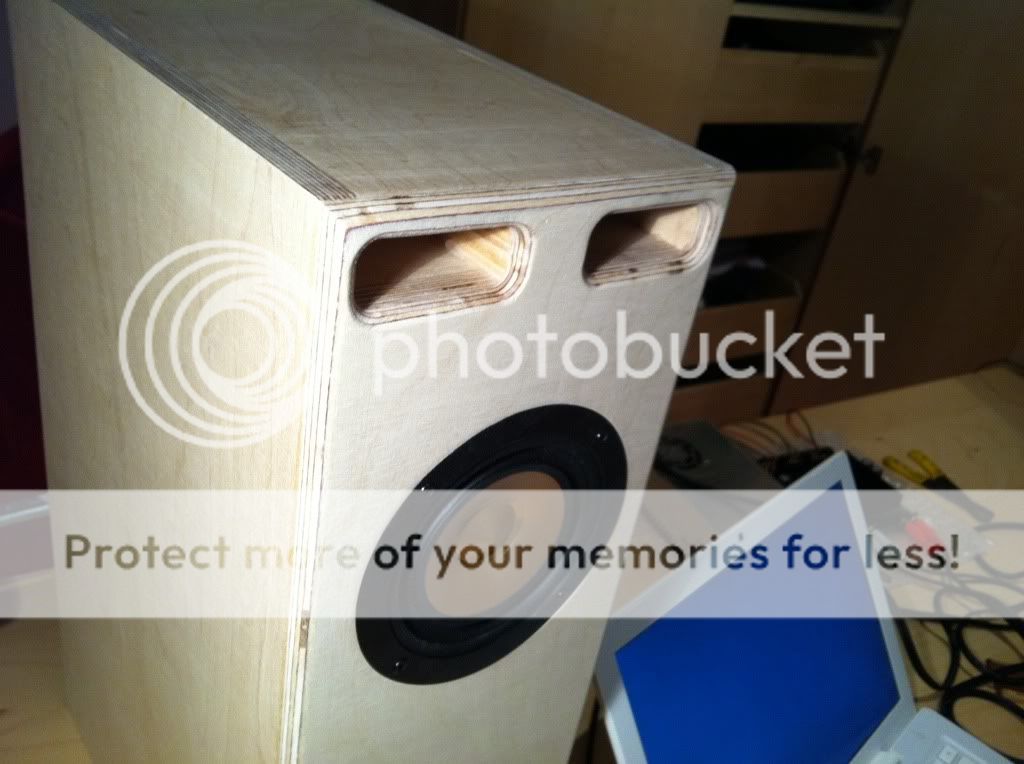
Hey guys, just built these:
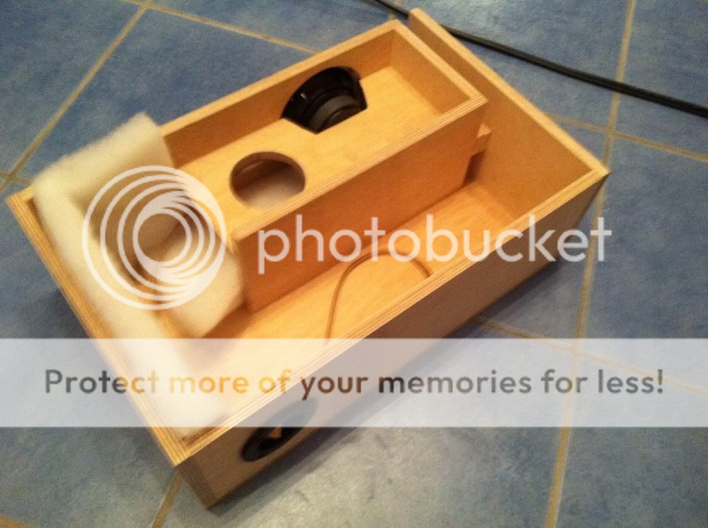

Here they are taped up with masking tape, to try to get an idea how much stuffing is necessary:
Once I make a finalized decision on the stuffing, and glue on the side wall, I'm going to add on a proper baffle to the front, so that the driver will be flush mounted, and so the grain of the plywood is covered up (and to add a roundover).
So far I'm pretty happy with what they can do at such a low price, and small form factor.
I will be using them as desktop computer speakers. So far I'm quite pleased, but I'm reserving final judgment for when I'm done. Very easy build (one evening's work).
I'm just finishing my budget, sealed CHR-70s and was wondering if anyone uses CAT5 wiring as speaker cables. I've seen TNT Audio writings on different configurations (for example, here) but does anyone have preference or practices they've used in the past? This would mainly be a temporary wire straight out of the enclosure and to my amp.
... was wondering if anyone uses CAT5 wiring as speaker cables...
A pair of single strands.
dave
Hey guys, just built these:
Here they are taped up with masking tape, to try to get an idea how much stuffing is necessary:
Once I make a finalized decision on the stuffing, and glue on the side wall, I'm going to add on a proper baffle to the front, so that the driver will be flush mounted, and so the grain of the plywood is covered up (and to add a roundover).
So far I'm pretty happy with what they can do at such a low price, and small form factor.
I will be using them as desktop computer speakers. So far I'm quite pleased, but I'm reserving final judgment for when I'm done. Very easy build (one evening's work).
Nice! Those look great! What are you going to be using to power them?
Scott
I use cheap(ish) 5 gauge wire designed for power car audio amps to hook up my speakers after doing high power testing of small transformers (10A -15A currents) and looking though a thermal camera and seeing 30c temperature rises in the wires that were about the thickness of normal cheap speaker cable (fractions of a mm). The wire says silly things on it and has 'directional' markings but is very substantial. Stuff like this:
4 AWG GAUGE 23 FEET RED POWER GROUND AMP WIRE AMPLIFIER on eBay (end time 06-Jan-11 19:22:00 GMT)
4 AWG GAUGE 23 FEET RED POWER GROUND AMP WIRE AMPLIFIER on eBay (end time 06-Jan-11 19:22:00 GMT)
Nice! Those look great! What are you going to be using to power them?
Scott
Thanks!
I'm powering them with a Tripath TA2024 based Class-D amp by Dayton. Perfect for desktop volume without taking up desktop space.
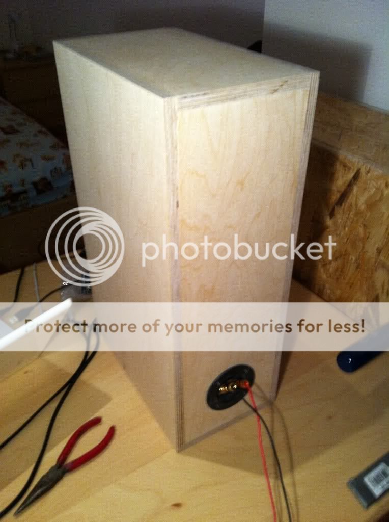
I glued up the speakers today, and put a 6.5mm thick suprabaffle on the front, covering up the endgrain of the side walls, and making the driver flush mounted.
Added some roundovers and I'm good to go. All I have left to do is paint it with a clear coat, since the birch finish nicely matches my birch veneered desk already.
An externally hosted image should be here but it was not working when we last tested it.
Not perfect routing, but good enough for me:
An externally hosted image should be here but it was not working when we last tested it.
Some endgrain on the back:
An externally hosted image should be here but it was not working when we last tested it.
Imaging on these things is pretty nice, I have them setup slightly wider than the typical 60degree stereo triangle, on some songs it sounds like instruments are coming from behind the speakers, that's quite startling.
These are folded transmission lines, for which I adapted the plans from plans available on planet10's site, but I can't for the life of me find the original plans anymore.

In anycase, pretty good speakers for 50 bucks a pop.
These are folded transmission lines, for which I adapted the plans from plans available on planet10's site, but I can't for the life of me find the original plans anymore.
Reminds me that i need to get the folded halfTower plans into the microTower plans (or as an appendix). Only links to the plans are in this earlier post.
dave
Reminds me that i need to get the folded halfTower plans into the microTower plans (or as an appendix). Only links to the plans are in this earlier post.
dave
Okay, I found the original post (even though the link doesn't work - probably because we have a different posts per page setting).
Skinny folded halfTower with front exiting terminus.
An externally hosted image should be here but it was not working when we last tested it.
folded halfTower 0v8 map
Someone build it and report back.
OK, here's James in Bavaria reporting back:
The speakers I built were adapted somewhat by myself. I tried to stay fairly true to the original, comparing differences in HornResp (not an accurate sim, but it shows how much changing a dimension changes the response). Here's a Sketchup of the actual model I built:
An externally hosted image should be here but it was not working when we last tested it.
An externally hosted image should be here but it was not working when we last tested it.
It's 12mm birch ply, with a 6.5mm thick baffle on the front (in addition to the 12mm thick front wall already in place, meaning total 18.5mm baffle)
For the port divider I used two pieces of 10x30mm pine wood glued together, and sawed to length.
Here are the exact dimensions:
An externally hosted image should be here but it was not working when we last tested it.
An externally hosted image should be here but it was not working when we last tested it.
I'm pretty sure these dimensions are unambiguous and complete, considering they were all I had to use when I built the speakers, having lost the original plans.
Perhaps if anyone would be so kind, they could model my speaker with the appropriate worksheets, to see what kind of output I should be expecting.
As for what kind of output I get? They hit pretty hard all the way down into the 40s, before rolling off. Plenty loud for the ~60cm distance I have from ear to speaker, I'm very happy with them as desktop speakers.
Last edited:


My clones of the black beauty design (page11) are finished apart from baffle step corection circuit which I am currently doing using EQ in software. I changed the external dimensions to 15x15x30cm with an 18mm baffle and 12mm sides. I also added an internal brace and plan on some changes to the baffle step circuit for my particularly close to wall situation.
I am very impresed by the frequancy range these speakers are capable of, bass exstension seems the same as my previous mission 760i's (about 80Hz). Imaging is superb especialy at close listening distances where two ways just wern't working corectly. They are also alot less 'boomy' than my previous speakers I presume due to the low group delay over the pass band compared with a ported design. Anyway I will do some actual mesurments at a latter date. Max volume is limited before distortion but more than loud enough for bedroom usage.
Burn in time for the CHR-70 I found to be about 10hrs, sound was very harsh and lacking in bass slightly to start with but I left them running for a day and came back and all was well.
apologies for the poor picture quality I only have a mobile phone (poor student). Many thanks to Henkjan for showing the capacitor equalised undersized boxes work well with this driver!
Attachments

- Status
- This old topic is closed. If you want to reopen this topic, contact a moderator using the "Report Post" button.
- Home
- Loudspeakers
- Full Range
- Mark Audio CHR-70 Application Thread