i/v gain stage
hi was just wondering if this would give similar results to rays output satge? http://diyparadise.com/ssiv.html
thanks
chris
hi was just wondering if this would give similar results to rays output satge? http://diyparadise.com/ssiv.html
thanks
chris
It is a different circuit but im sure the overall benefits from this pcb are similar to the "Discrete" pcb. The discrete pcb uses 2SK170 fets and these are superb audio transistors. Also the filter section in the discrete is designed for the cd 63 67 in particular.
Build them both and see what you like or Discrete
Brent
Build them both and see what you like or Discrete
Brent

rowemeister said:It is a different circuit but im sure the overall benefits from this pcb are similar to the "Discrete" pcb. The discrete pcb uses 2SK170 fets and these are superb audio transistors. Also the filter section in the discrete is designed for the cd 63 67 in particular.
Build them both and see what you like or Discrete
Brent
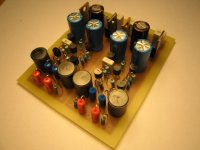
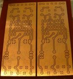
Another one ready to rock.
Attachments
Re: i/v gain stage
That is an I/V conversion stage for an unbalanced current-output DAC (Philips TDA1545A) which has a single current output per channel.
The DAC in the CD-63/CD-67 is a differential voltage-output DAC. (NPC SM5872BS). It has two voltage outputs per channel.
They couldn't be more different from each other, and require totally different output stages. Also there is very little filtering on the I/V converter (1st order). Ray's stage has a 3rd-order filter which is necessary on this type of DAC which outputs a raw PWM signal. It is basically a 16.9MHz square wave with the audio signal (and loads of unwanted HF garbage) superimposed on it. (A very simplified way of putting it.)
Hope this helps!
Glenn
reddish75 said:hi was just wondering if this would give similar results to rays output satge? http://diyparadise.com/ssiv.html
thanks
chris
That is an I/V conversion stage for an unbalanced current-output DAC (Philips TDA1545A) which has a single current output per channel.
The DAC in the CD-63/CD-67 is a differential voltage-output DAC. (NPC SM5872BS). It has two voltage outputs per channel.
They couldn't be more different from each other, and require totally different output stages. Also there is very little filtering on the I/V converter (1st order). Ray's stage has a 3rd-order filter which is necessary on this type of DAC which outputs a raw PWM signal. It is basically a 16.9MHz square wave with the audio signal (and loads of unwanted HF garbage) superimposed on it. (A very simplified way of putting it.)
Hope this helps!
Glenn
avr300 said:
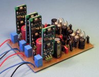
Another one ready to rock.
Are those Toko 10RB shielded inductors?
I just got hold of some of these (the 5% 'J' ones) and it took me bloody ages to find them!
The ones I used before picked up hum and I'm hoping these will cure it.
Glenn2 said:
Are those Toko 10RB shielded inductors?
I just got hold of some of these (the 5% 'J' ones) and it took me bloody ages to find them!
The ones I used before picked up hum and I'm hoping these will cure it.
They might be, compared to Toko' web, they do look similar. They are indeed shielded.
I don't get any pickup what so ever - not anything else than sweet music.
Perhaps I doubted you who said, that there was more beyond a hotrod opamp. There is. A discreet filter and buffer. I am hearing things now (from the record) that I couldn't hear before. There is just more of everything now. More music!
Thx. Ray and anyone else who has been involved in this output stage. Great work.
, big avr300 said:Shhhh, it's still into surgery.
Ah, apparently the surgery worked
.More music, that's good to hear, you're welcome!
Just wait till you try some low-noise regs and other fancy components...
Regards,
Ray
Attachments
6h5c said:
Ah, apparently the surgery worked
More music, that's good to hear, you're welcome!
Just wait till you try some low-noise regs and other fancy components...
Regards,
Ray
I second that
Brent
Re: ground plane
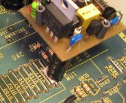
Hi Chris,
You could screw it down, but most of the times there's no room for drilling fixing holes in the player's PCB without damaging the copper traces. Or you could short-circuit things with a metal bolt or nut. I usually glue a few distance studs to the underside of the PCB-to-be-added and then fix it to the main PCB with glue or small pieces of double-sided foam tape. Or I use tape on top of the HDAM cans or the electrolytics combined with some studs.
Regards,
Ray
reddish75 said:hi this may seem like a stupid question but im quite a noobie at this, if i make a circuit board for the output stage how would i fit it in the player, could i screw it down or will this mess up the grounding, if you know what i mean?
thanks
chris
Hi Chris,
You could screw it down, but most of the times there's no room for drilling fixing holes in the player's PCB without damaging the copper traces. Or you could short-circuit things with a metal bolt or nut. I usually glue a few distance studs to the underside of the PCB-to-be-added and then fix it to the main PCB with glue or small pieces of double-sided foam tape. Or I use tape on top of the HDAM cans or the electrolytics combined with some studs.
Regards,
Ray
Attachments
http://rswww.com/cgi-bin/bv/rswww/s...mhekddjlcefeceeldgondhgf.0&cacheID=uknetscape
This one has lower resistance but same inductance
Lee
This one has lower resistance but same inductance
Lee
Hi,
I assume these are Farnell part numbers not RS ?
http://uk.farnell.com/jsp/displayProduct.jsp?sku=1193619
http://uk.farnell.com/jsp/displayProduct.jsp?sku=1077043
Cheers,
Jon
I assume these are Farnell part numbers not RS ?
http://uk.farnell.com/jsp/displayProduct.jsp?sku=1193619
http://uk.farnell.com/jsp/displayProduct.jsp?sku=1077043
Cheers,
Jon
JonHarrison said:Hi,
I assume these are Farnell part numbers not RS ?
http://uk.farnell.com/jsp/displayProduct.jsp?sku=1193619
http://uk.farnell.com/jsp/displayProduct.jsp?sku=1077043
Cheers,
Jon
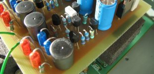
Yup, that they are. Any ideas on the best to use? I have just made these and want to get cracking.
Anyone, what's the best way to stop the boards oxidising?
Cheers, Lee.
Attachments
- Home
- Source & Line
- Digital Source
- Marantz CD63 & CD67 mods list