Malefoda said:Icing on the cake?
We french people say "cerise sur le gâteau", cherry on the cake
Mmm, French cakes...

Thanks guys.
I listened to it for the first time last night, and the improvement over the previous stage is clearly noticeable. First I used standard CF1/4 carbon resistors and output caps that I had laying around. Although the sound improved over the opamps, it was still sounding a bit dull compared to how it sounds now ! Vocals are very clear, even more small detail is revealed, like the small noises that surround an 's' or a 't', and guitar strings and cymbals. Low-end is powerful and tight, not sloppy or over-present. Can't wait till I fit a Flea in this one too!
I used the Holco's earlier in my stepped attenuator and I like it very much, so I thought let's give it a try here. I've had good experiences with tin-foil caps in the cross-overs of my speakers, so I chose the PPFX-S. Those are also the most expensive parts . Almost 80 bucks for two of them... But I think this stage deserves it.
Regards,
Ray.
I listened to it for the first time last night, and the improvement over the previous stage is clearly noticeable. First I used standard CF1/4 carbon resistors and output caps that I had laying around. Although the sound improved over the opamps, it was still sounding a bit dull compared to how it sounds now
! Vocals are very clear, even more small detail is revealed, like the small noises that surround an 's' or a 't', and guitar strings and cymbals. Low-end is powerful and tight, not sloppy or over-present. Can't wait till I fit a Flea in this one too!I used the Holco's earlier in my stepped attenuator and I like it very much, so I thought let's give it a try here. I've had good experiences with tin-foil caps in the cross-overs of my speakers, so I chose the PPFX-S. Those are also the most expensive parts
. Almost 80 bucks for two of them... But I think this stage deserves it.Regards,
Ray.
Ray, the much talk about group delay in the original filter (round about post 9xx) - did you ever have a conclusion whether it was worth retuning the filter or not? You did those fine simulations.
Another thing is Pedja's advice to downcap the digital line, http://www.pedjarogic.com/cd_mods/index.html,
Quote:
"Better PS filtering in the digital means cleaner sound. I put to this player's digital lines not often used Capxon GL, low-ESR, low-Z series (100uF, actually lower values than those which player originally had), they are quite cheap and work surely (far) better than originally used Elna standard series. While we still have to understand the logic behind the caps value in the amplifiers, it is sure that the old “use bigger value caps” tweaking strategy is completely wrong in digital. (Yes, I tried. I had big, slow sound using 1000uF at the digital lines.) What is mandatory here is the cleaning of the lines; voltage is already nicely smoothed by any active regulator and nothing here demands a reserve in power."
Quote end.
Is he ref'ing C815? Right now I'm using 100u FC here, down from 3900u FC. Needs more time to tell.
SimontY said:Expensive but worthwhile then Ray, you sound very happy
Yes, very happy Simon
It's playing right now...
Re: Re: Re: CD Enhancer
Lol simon, soo true.
SimontY said:
If I were you I'd concentrate on getting a player working..........
Simon
Lol simon, soo true.avr300 said:Ray, the much talk about group delay in the original filter (round about post 9xx) - did you ever have a conclusion whether it was worth retuning the filter or not? You did those fine simulations.
Another thing is Pedja's advice to downcap the digital line, http://www.pedjarogic.com/cd_mods/index.html,
...
Is he ref'ing C815? Right now I'm using 100u FC here, down from 3900u FC. Needs more time to tell.
Hi avr,
The final filters as I use them right now are here in post 933. Oh yes, the good old days of post 933...
The conslusions I made back then still stand. Overall the sound is more relaxed and the highs seem cleaner. I also inserted the notch filter in my '67, but I didn't notice any big differences (yet?).
I think Pedja is referring to the caps directly near the IC's. I've heard before that using 1000u there doesn't do any good. Most of the times I use a value somewhere between the original and the double of that. Depends a bit on the size and how it fits.
Regards,
Ray.
Well i killed my cd53 Just finished all the mods to the analog stage and power supply. Put the player bvack together and it was playing fine and sound truly amazing the best ive heard digital sound! But aparently a peice of a lead that i cut stuck to the botom of the board and when i moved the player it short something out, first the laser was buzzing and hopping around like crazy and said error 12 then it just deid and keeps blowing fuese Anyone have a player they want to sell me cheap?? I actually just need the main board, I have a case from my 53 and the 63se I had years ago. At least i have lotsa extra parts, I now have two spare transports and trannies! but Im pissed cuz I had it sounding so damn good and a stupid little mistake and i freid it Im looking for another on ebay and theres a few 63 and 67 but they are a little pricey. Any other players that are good modding candidates?? Ive heard the Rotel rdc865 or 965bx are quite good, i think ther Dac is a saa7323?
Just finished all the mods to the analog stage and power supply. Put the player bvack together and it was playing fine and sound truly amazing the best ive heard digital sound! But aparently a peice of a lead that i cut stuck to the botom of the board and when i moved the player it short something out, first the laser was buzzing and hopping around like crazy and said error 12 then it just deid and keeps blowing fuese Anyone have a player they want to sell me cheap?? I actually just need the main board, I have a case from my 53 and the 63se I had years ago. At least i have lotsa extra parts, I now have two spare transports and trannies! but Im pissed cuz I had it sounding so damn good and a stupid little mistake and i freid it Im looking for another on ebay and theres a few 63 and 67 but they are a little pricey. Any other players that are good modding candidates?? Ive heard the Rotel rdc865 or 965bx are quite good, i think ther Dac is a saa7323?avr300 said:...
Is he ref'ing C815? Right now I'm using 100u FC here, down from 3900u FC. Needs more time to tell.
AVR,
Power supplies make great mods for analog and digital consumers.
I had good results designing PSUs with low capacitance to maintain both minimal load currents and fast recovery. Take only the best available and try to keep internal resistance minimal. Short connections are beneficial but sometimes unpractical. For this reason and for seperating different consumers you need decoupling caps. Start with a low value (10uF) as currents might be modest and increase to a point there's no more audible gain. Best results are obtained when you use decoupling caps in ratio to the current. To find the optimum one has to measure every individual consumer current for a PSU

Regards, Jaap
If anyone has a spare main board or whole cd53/63 they want to sell let me know.
I beleive Audiocom is just on holiday, they will be back to ebay in a few weeks. But I also found out they dont ship to the US because of conflicts wqith thier dealers here in the states So no good deals for me. That stinks I was going to buy a bunch of the super regulators at the ebay price. Im going to look into those Burson Audio guys they have discrete super regs for around $18USD each on ebay, Ill give them a try when i get another cd63 to mod.
You could also try one of those $30 clocks from these guys, i want to try one and see how it is, but I cant now untiol I get a new cd53.
inexpensive clock upgrade
and as bad news calls bad news, no more good deal from Audiocom on eBay, Superclock II is gone... and its price also...
I beleive Audiocom is just on holiday, they will be back to ebay in a few weeks. But I also found out they dont ship to the US because of conflicts wqith thier dealers here in the states
So no good deals for me. That stinks I was going to buy a bunch of the super regulators at the ebay price. Im going to look into those Burson Audio guys they have discrete super regs for around $18USD each on ebay, Ill give them a try when i get another cd63 to mod.You could also try one of those $30 clocks from these guys, i want to try one and see how it is, but I cant now untiol I get a new cd53.
inexpensive clock upgrade
Just wanted to add that before my player died I got to listen to a few cd's and I must say it was sounding really amazing and wasnt even broken in yet. Heres a list of what I had done
Power Supply:
-c803/804 2200/35 Pana FC+.1uf film
-c806/806 1500/16 Pana FC+.1uf
-c813 4700/16 FC+1uf
-c814 3300/16v FC+.1uf
-c815 4700/6.3 FC+.1uf
-D801-804 11dq10 Schottky
-D811-814 11dq10 Schottky
-Choke + .47uf X2 cap on AC input
-Chokes+feritte beads on all power feed resistors
Analogue Stage:
-Opamp AD827 + 4x1000uf FC+.1uf wima
-all caps in filter stage are 1% polystyrene
-all resistors are .1% Dale RN55
-removed muting transistors
-removed output caps
Digital section:
-"Clock Hack"
-.1uf smd XR7 caps on power pins of Dac/Decoder
all decoupling caps replaced with Rubycon ZL/ZA+.1uf smd XR7
Mechanical:
-damped transport and chassis with bitumen
-bottom plate sandwhich of two sheets of aluminum plate(1/8in) with foam damping sheet in between
-adjustable cone feet
So I guess Im going to have to pull all the parts and start over when I get a new cd63. I cant wait to hear what it sounds like with a good clock, the regulator mod and some super regulators for the opamps!!! Hopefully my next attemp will work out better than this one! than you guys for all the help you have given me.
imperfectcircle said:... aparently a peice of a lead that i cut stuck to the botom of the board and when i moved the player it short something out, first the laser was buzzing and hopping around like crazy and said error 12 then it just deid and keeps blowing fuese
Just two thoughts ....
You've put beads on the 4.7 ohm / 0.25W resistors. Make shure they are isolated from the ground plane.
If not causing the trouble, next:
Remove the 4.7/0.25 resistors one by one to isolate the short. Go from there for repairs.
Jaap
Re: Re: Clock signal from DAC to Decoder
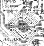
It's even worse. On the 63 the schematics and the actually layout round the decoder is a mess. The scematics is correct according to the datasheets. Pin14 CROUT is connected via i 1M resistor to Pin13 - like they had planned a local resonator for the decoder. My silkscreen says RD14 or C521 - and there is a ceramic cap in this place.
U192 is factory replaced with a res. 390R
It's the same my CD53 and in my 63SE.
I'll lift the 1M and RD14/C521 and connect my Flea to this point.
Am I overlooking something here (just before I'll start soldering).
rowemeister said:
The CD63 also has a similar error on the 5v rail where pin 15 is direct from 7805 and not through the resistor. Something to change when fitting regs.
The blue link shows where it actually goes and not how the diagram shows
I cut the track and link out
Brent
It's even worse. On the 63 the schematics and the actually layout round the decoder is a mess. The scematics is correct according to the datasheets. Pin14 CROUT is connected via i 1M resistor to Pin13 - like they had planned a local resonator for the decoder. My silkscreen says RD14 or C521 - and there is a ceramic cap in this place.
U192 is factory replaced with a res. 390R
It's the same my CD53 and in my 63SE.
I'll lift the 1M and RD14/C521 and connect my Flea to this point.
Am I overlooking something here (just before I'll start soldering).
Attachments
Well, without the 1M between pin 13 and 14 and the C523 from pin 14 to gnd, it won't spin. So there IS an incorrect between the schematics and the "real world" - because the schematics won't run!
So, is the decoder sensetive to jitter and do the DAC clk out introduce jitter - in other words, is it worth getting the direct clock from my Flea to drive the decoder or should one stick with the factory solution.
So, is the decoder sensetive to jitter and do the DAC clk out introduce jitter - in other words, is it worth getting the direct clock from my Flea to drive the decoder or should one stick with the factory solution.
Re: Re: Re: Clock signal from DAC to Decoder
In figure 26 (page 32) there are three oscillator circuits. It seems Marantz cut the costs of the extra parts by using the main clock. I noticed there exist several versions of the SAA7345. It might explain the 'freewheeling' RD14/C521 at the DAC for freedom of choice, possibly to correct a problem regarding input capacitance. See page 28 of SAA7345 datasheet for details on CRin/CRout.
Jaap
avr300 said:It's even worse. On the 63 the schematics and the actually layout round the decoder is a mess. The scematics is correct according to the datasheets. Pin14 CROUT is connected via i 1M resistor to Pin13 - like they had planned a local resonator for the decoder. My silkscreen says RD14 or C521 - and there is a ceramic cap in this place.
U192 is factory replaced with a res. 390R
It's the same my CD53 and in my 63SE.
I'll lift the 1M and RD14/C521 and connect my Flea to this point.
Am I overlooking something here (just before I'll start soldering).
avr300 said:Well, without the 1M between pin 13 and 14 and the C523 from pin 14 to gnd, it won't spin. So there IS an incorrect between the schematics and the "real world" - because the schematics won't run!
So, is the decoder sensetive to jitter and do the DAC clk out introduce jitter - in other words, is it worth getting the direct clock from my Flea to drive the decoder or should one stick with the factory solution.
avr300 said:The board layout in the manual corresponds to the schematics, pin 14 is NC - but not to the board in my hand.
In figure 26 (page 32) there are three oscillator circuits. It seems Marantz cut the costs of the extra parts by using the main clock. I noticed there exist several versions of the SAA7345. It might explain the 'freewheeling' RD14/C521 at the DAC for freedom of choice, possibly to correct a problem regarding input capacitance. See page 28 of SAA7345 datasheet for details on CRin/CRout.
Jaap
emove the 4.7/0.25 resistors one by one to isolate the short. Go from there for repairs.
Thanks Disco for the tip. Im going to start with the servo section since thats where the short happened. Im just hoping it something simple. I already treid replacing the 3 opamps and servo chip from an extra board I had, and it does the same thing. So I guess Ill have to start removing the resistors one a t a time to find where the problem is.
Before it started blowing fuses i got erro message 12 which is a sled error any ideas what would cause this?? I treid a differant transport and got the same result.
thanks
Frank
- Home
- Source & Line
- Digital Source
- Marantz CD63 & CD67 mods list