It works, it actaully works! first time! I could cry!
Thankyou so much every one especially Shoog and Eli.
I've got quite a few things to tweek; like the right channel coming out of the left and the left coming out of the right but it actually works and it sounds great.
I'd better go and lay the carpet I was supposed to lay two weeks ago!
Thanks again, I'll report back in more detail tomorrow!
The good news is not surprising. The ducks were carefully lined up and the superior build quality reflects a general familiarity with DIY work. Obviously, your SS experience is substantial.
I hope you realize that tubes/valves are a (sic) lifetime addiction.
")
Well I've got the amp into my system and I've run a fair bit of Nina Simone, Jonny Cash and Hayden through it and I've now gone back to the Nad's Pre for a while; the best summary i can give the sound is that it makes the NAD sound Gutless! I really like it! that said there's loads of problems! most I'm pretty sure I can get to the bottom of, the one thats really bad though is the transformer is buzzing like hell, the chasis is actually vibrating so much you can hear it from a meter away; this is the effect of an overloaded transformer? I need to investigate further because it shouldn't be even nearly overloaded!
If the transformer doesn't buzz under no load then the transformer is OK. Disconnect the rails and check. Then add in the rectifiers and test again.
You may have just discovered why the amp was junked in the first place as it is mostly likely that one of the caps has gone leaky and represents a short to ground.
So the first thing to do is to check current draw before and after each cap bank - if they are different then there is your problem. Place your multimeter in series with the rails. Total current on each rail should be just 16mA or so.
It is fairly unlikely to be the circuit itself.
Shoog
Nuts! I am Death to transformers.
I dissconnected the transformer, it hums a lot less, but it still hums bad; Looks like I've overoaded it, and/or its just cheap rubbish. It still supplies the correct voltage though!
I should never have used old caps I've been warned about them in the past.
I guess I'll take this oppotunity to build a nice power supply; I was thinking I'd build a seperate supply out of the chasis and feed +/-50vAC and the 6vAC into the main chasis and then rectify there, removing the transformer will leave me plenty of room for big Caps;
Use four of these: Nichicon GY Audio Grade Capacitor 2200uF 160V and some schottky rectifying diodes.
What do you think?
I am wondering if you wired the bridge up to the transformer correctly. The center tap should have been referenced to earth, and the caps should then be referenced to that earth - no other power supply connection to earth. Also did you make certain the cap polarity was right. Cap neg to the neg rail on the neg supply and positive to earth, and cap pos to the pos rail on the positive supply with neg to earth. Stupid mistakes to make and you probably didn't do them, but easy enough.
I have recycled caps with only one or two failures in the past. Its always a good idea to check before using them but generally their good.
Where did you get your transformer as I can't believe its a faulty new one.
Don't panic and try to cure this with logical steps.
I think those caps would be OK (if their genuine). I wouldn't bother moving the supply offboard, it undoubtedly will not improve sonics at all.
Shoog
Last edited:
It's a Farnell branded transformer from CPC, 75VA, 0-230 Primary, 0-50 0-50 secondrys (wired in series using the link as the ctr tap)I am wondering if you wired the bridge up to the transformer correctly. The center tap should have been referenced to earth, and the caps should then be referenced to that earth - no other power supply connection to earth.
I'm 99.9% sure I have the cap polarity right and i reacon if it was wrong the cap would have hit the roof by now.Also did you make certain the cap polarity was right. Cap neg to the neg rail on the neg supply and positive to earth, and cap pos to the pos rail on the positive supply with neg to earth.
Really? If you touch it, the case is noticably vibrating.I wouldn't bother moving the supply offboard, it undoubtedly will not improve sonics at all.
Correct, with nothing attached to the transformer secondaries it still buzzes!That's a different problem. Once the power supply is working properly it will not buzz and so will not be an issue.
So just to clarifiy - with nothing attached to the transformer secondaries it still buzzes ?
Shoog
I haven't dug the board out yet, I'm going to get i out in the morning. I could hear a slight ticking sound coming from the cap area whem I power down. I assume one of them is dead.Have you checked each cap for leakyness ?
Shoog
Last edited:
I think those caps would be OK (if their genuine). I wouldn't bother moving the supply offboard, it undoubtedly will not improve sonics at all.
Shoog
People dont make fake caps surely??
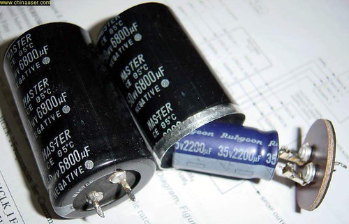
I've had a look at the old caps, It looks like a few have leaked; I didn't spot it at first because of the amount of brown glue Cambridge used to stick them down, but if you look close you can see where riverlets of electrolyte ran accross the original PCB years ago.
Last edited:
I've got CPC to send me a replacement transformer and I've ordered four of those 2200uF 160V Nichicon Caps.
I'm going to build somthing similar to the Duttman PSU from Page 3
 [/IMG]
Without the stacked caps obviously, fully rectified and without the RC circuit at the end (those Solens are expensive), the big cokes will be a future add-on!
Eli; how do I calculate the values of the RFChoke at the front of the circuit?
I'm going to build somthing similar to the Duttman PSU from Page 3
Without the stacked caps obviously, fully rectified and without the RC circuit at the end (those Solens are expensive), the big cokes will be a future add-on!
Eli; how do I calculate the values of the RFChoke at the front of the circuit?
Eli; how do I calculate the values of the RFChoke at the front of the circuit?
JBS,
You select a RFC which will not saturate from the DC draw placed on the rail. Parts which properly handle low preamp currents should be easy enough to source. I can't see where 1 mH. or larger valued RFCs will be at all troublesome.
Cobble a schematic of the PSU you intend to use together and post it, for the "crowd" to critique.
JBS,
You select a RFC which will not saturate from the DC draw placed on the rail. Parts which properly handle low preamp currents should be easy enough to source. I can't see where 1 mH. or larger valued RFCs will be at all troublesome.
Just to make sure I understand this circuit; is the RFC and the 1nF cap are forming a 2nd order lowpass filter to block HF noise from the mains power?
The RFC availible from Maplin states a Max DC of 170mA and I shouldn't be pulling more than 20mA through it, I assume thats what you mean by saturation point.
This is the circuit I have i mind:

All 4 Ecectrolytic Caps are the same 2200uF/160V. and the Chokes are liked out untill I can accure some from somwhere
Just to make sure I understand this circuit; is the RFC and the 1nF cap are forming a 2nd order lowpass filter to block HF noise from the mains power?
The RFC availible from Maplin states a Max DC of 170mA and I shouldn't be pulling more than 20mA through it, I assume thats what you mean by saturation point. All 4 Ecectrolytic Caps are the same 2200uF/160V. and the Chokes are liked out untill I can accure some from somwhere
Maplin's WH47B RFC should do, as long as it has adequate current handling capability.
While the "hash" filter will attenuate trash that sneaked in from the AC mains, that's not the primary purpose. A tiny conduction angle is present, when large valued parts are used in a cap. I/P filter. When the conduction angle is tiny, the ripple waveform is sharp and "triangular". Per Fourier's Theorem, such a waveform contains high order overtones of the ripple fundamental, which extend well up into RF. That "crud" is the primary target of the "hash" filter.
Use 100 Ω resistors as the links, until inductors are sourced.
Unless a negative temperature coefficient (NTC) inrush current limiting thermistor is installed between the power trafo's CT and the ground bus, the 50 mA. fuses will fail at power on. An untamed start up surge will be MASSIVE.
Unless a negative temperature coefficient (NTC) inrush current limiting thermistor is installed between the power trafo's CT and the ground bus, the 50 mA. fuses will fail at power on. An untamed start up surge will be MASSIVE.
I have a couple of these on some old swichmode PSU's labled SCL 055 (5ohms at 25'C max 5A); usable?
Commercial ECC86 preamplifier
You are not the only ones using ECC86, see this report: Stereophile: Battery-Powered Tube Preamp from Siltech
You are not the only ones using ECC86, see this report: Stereophile: Battery-Powered Tube Preamp from Siltech
... they are ECC86 dual-triodes, which were developed for car-audio and microphone use. ... It also offers very low 1/f noise for a small-signal tube
You are not the only ones using ECC86, see this report: Stereophile: Battery-Powered Tube Preamp from Siltech
$28,000, and god it's ugly!
I have a couple of these on some old swichmode PSU's labled SCL 055 (5ohms at 25'C max 5A); usable?
I don't think so. Cold resistance is low and the part will never heat up. See if Maplin or Farnell has Epcos B57153S330Ms. That part is 33 Ω/25o, with an Imax. of 1.3 A. If you wrap a B57153S330M in wool or acrylic yarn and encapsulate in heatshrink, a reasonable temperature rise can be expected.
- Status
- This old topic is closed. If you want to reopen this topic, contact a moderator using the "Report Post" button.
- Home
- Amplifiers
- Tubes / Valves
- Low Voltage Tube Preamplifier