SMPS are great sources for 200uf 200V caps which are very useful for Preamp service. I used to collect them by the dozen from the computer repair shop. They also have useful fast soft recovery recifiers, and are great for their bundles of multicoloured wire - which I have never had to buy as a result.
Shoog
Shoog
nd are great for their bundles of multicoloured wire
oh yes. My pre-amps are full of the re-used wires from just 1 SMPS I had.
")
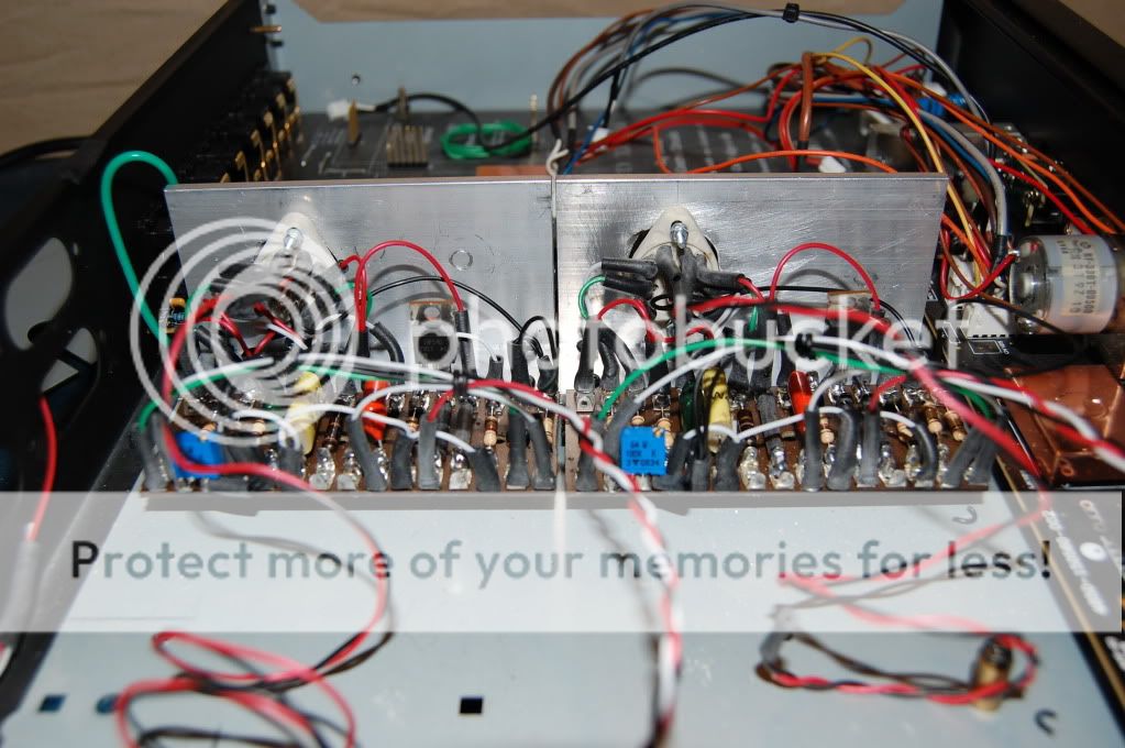
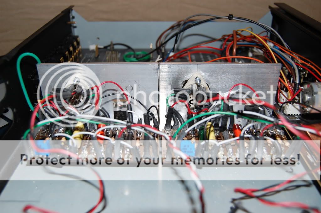
This is my first Valve build, any comments?
I generally use the tube socket terminals to hang the resistors and capacitors on, instead of lengths of wire going to remote terminals. Less stray capacience, and less stray hum pickup. Otherwise it looks great.
How did the exam go?Not at the moment. I am on holiday and revising for an exam on Thursday, so I tend to hover. I've just switched my computer sound system over from a Gainclone to a valve amp and the results are very good, so I have the computer on for background sounds. What more could I want.
Shoog
First one went well. The major dramas was getting there.
Environmental physics today - shouldn't be to hard.
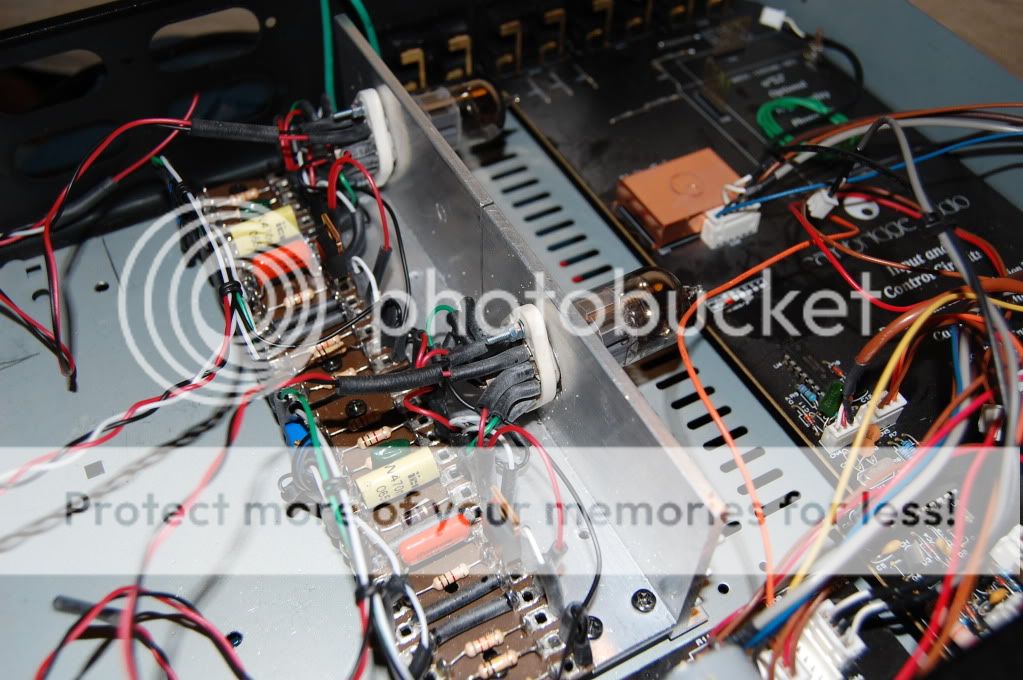
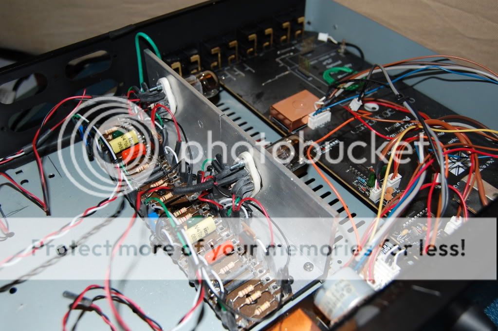
Have you hooked the baby up yet. I would go with the last comment, better to use the pins for component attachment. ECC88's are notorious for high frequency instability which is difficult to diagnose. If the sound is harsh at all then its high frequency instability. This can usually be solved by wiring a 100R resistor straight on the grid pin.
Lovely build, but its the sounds that matter
Shoog
Environmental physics today - shouldn't be to hard.
Have you hooked the baby up yet. I would go with the last comment, better to use the pins for component attachment. ECC88's are notorious for high frequency instability which is difficult to diagnose. If the sound is harsh at all then its high frequency instability. This can usually be solved by wiring a 100R resistor straight on the grid pin.
Lovely build, but its the sounds that matter
Shoog
First one went well. The major dramas was getting there.
Environmental physics today - shouldn't be to hard.
Have you hooked the baby up yet. I would go with the last comment, better to use the pins for component attachment. ECC88's are notorious for high frequency instability which is difficult to diagnose. If the sound is harsh at all then its high frequency instability. This can usually be solved by wiring a 100R resistor straight on the grid pin.
Lovely build, but its the sounds that matter
Shoog
You mean move the 100R off the tag board and have it straight onto the valve pin? or do you mean an additional 100R?
It makes almost no practical difference since the input impedance of the grid is in the megohms range. So in order to save desoldering just insert one into the wire run - wrap the resistor lead around the pin such that the body of the resistor is touching the pin. You can cover the body of the resistor in one of those sleeves to save shorting it out later. Remember there are two grids to deal with - one for the bottom CCS as well - instability will propergate throughout the amp. The 1K on the gate of the Mosfet can also be a source of instability so make certain it is also on the pin.
Physics was a breeze, two down one to go. Then I can get on with finishing my super mega smashing 6AS7 amp - joy joy.
Shoog
Physics was a breeze, two down one to go. Then I can get on with finishing my super mega smashing 6AS7 amp - joy joy.
Shoog
Last edited:
PSU finished; and I walked in to work yesterday and the first old PSU I layed my hand on was a 6VAC 1.8A inytercom PSU; that seems a bit too lucky!
As for the rest of the circuit, I have a fuse for B+ and a fuse for B-; what value fuse should I be using here? will 250mA do it?
As for the rest of the circuit, I have a fuse for B+ and a fuse for B-; what value fuse should I be using here? will 250mA do it?

That would be fine. I usually only have one master fuse.
Should be up and running today - the suspense
Shoog
I am trying so hard not to rush through the last few connections and check everything properly!
Give me a couple of hours and I should be about there!
or on fire!
I'm ready to turn on, but my heater voltage is 7vac unloaded; is this ok?
I think you are good to go. Loading the heater supply will drop the voltage. If the voltage under load is in the 6.0 to 6.6 V. range, you are surely fine, as that's less than a 5% deviation from the "norm".
6.67v under load!
Too much?
You are probably fine, as the reading is less than 6% high. Many types will tolerate as much as 10%.
5% is quite conservative.Is the main problem reduced tube life?
Yes.
You could add some resistance in parallel with the supply, to load it down a bit more.
6922s draw 300 mA. of heater current, each. Instead of using 1 or more dropping resistors in series with the heater supply, a single, well chosen, resistor in parallel with the heaters will provide additional loading to reduce the voltage present. A 5 W. rated 22 Ω metal oxide part might get the job done.

Thankyou so much every one especially Shoog and Eli.
I've got quite a few things to tweek; like the right channel coming out of the left and the left coming out of the right but it actually works and it sounds great.
I'd better go and lay the carpet I was supposed to lay two weeks ago!
Thanks again, I'll report back in more detail tomorrow!
- Status
- This old topic is closed. If you want to reopen this topic, contact a moderator using the "Report Post" button.
- Home
- Amplifiers
- Tubes / Valves
- Low Voltage Tube Preamplifier