Sound cards are different. If you got one with the good ADC chip, then you can relatively easy modify this card for the better performance. My modified Asus Xonar D2 with the CS5381 works fine. I can trust it to -125dB...-130dB levels in the direct measurements.
This is well and good but trying to take data at -125dB levels in the presence of 0dB signals is an unnecessary burden. BTW that still represents a fairly high noise floor (~100's of nV/rt-Hz)
The notched normal mode output of your THD analyzer should work fine with a sound card if you amplify it by a known amount, say 40dB and take that into account. I did this with a Sound Technology 1700B 25yr. ago. That instrument became a poor man's AP with the addition of passive L/C filters and twin-t's. OPA-134 should be fine for this.
Are we wrong to assume that if the range of the 725 is set -100dB FS and the monitor output is scaled to 0dB FS that we have 100dB of gain on the measurement. If ARTA has been calibrated for 0dB FS then we can simply subtract 100dB from the apparent displayed levels in ARTA.
The level appears to agrees when tested by mixing in a pilot tone at a known level but the apparent noise doesn't add up.
Aside from ARTA and the sound card, everything is LAB equipment.
What we am doing wrong?
I have found mistakes in the manuals.
Interesting, first I would find 100db of post processing gain a bit hard to handle. That would mean an amplifier with -80dB of seconds on a 1V input would put out 10V rms. Secondly I noticed some blocks in the Shibasuku labeled in a way that would indicate there is some automatic leveling going on (maybe?). Is it possible injecting an alien tone is fooling something.
You need to know the referred to input gain on the processed output. You are on the right track step back and do a one frequency sanity check where you can look at everything unambiguously.
Last edited:
I dont need to use the sound card QA401 for its ability below -100dbv. The amplified signal at the monitor output of the 725D works fine with a limited range sound card.
One way to keep the system from fooling you is to keep a fixed amplitude/freq known idle tone in play while measuring the DUT. It prevents any agc or similar range adjusting from happening which you didnt know was happening. The 725D has fixed gain/thd buttons to lock the gain etc. The Panasonic machines do Not and you can only know - if using the monitor output -- which range it is on by added that known idle tone level. it expects you to read out the thd /Im etc on the front panel. Which is accurate to -140dbv.
A notch filter is not needed in my case. However, back a couple years i went that route and still have the passive, variable freq notch filter made by B&K 1607. useful on HP339A also.
THx-RNMarsh
Last edited:
Interesting, first I would find 100db of post processing gain a bit hard to handle. That would mean an amplifier with -80dB of seconds on a 1V input would put out 10V rms. Secondly I noticed some blocks in the Shibasuku labeled in a way that would indicate there is some automatic leveling going on (maybe?). Is it possible injecting an alien tone is fooling something.
You need to know the referred to input gain on the processed output. You are on the right track step back and do a one frequency sanity check where you can look at everything unambiguously.
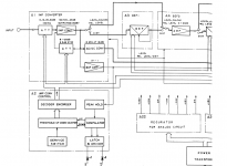
The Shibasoku has automatic input ranging. It looks at the fundamental input level and sets the input attenuation and gain of the impedance convertor (input amplifier) form that. This system is an independent circuit from the range switches on the from panel.
It sample at a bout 10 sample per second.
The operator has a choice of either automatic range selection of the front panel range switches or manual selection of the range switches. The frequency tuning of the 725 is done from frequency counter The 725 can be set to hold so the tuning doesn't change during a measurement. There is no phased locked auto tuning of the notch filters.
As long as the injected test tone is significantly lower level from the fundamental level, say -40dB below fundamental then, the 725 won't react to it. There no way a test tone equal to the fundamental level can be used.
The only difference I can see from level mode to distortion mode is the the notch filters are bypassed in level mode.
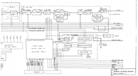
The block diagram from the operation manual doesn't show the gains of the 725 nearly as well as the service manual. I post service manual block now.
I can go through each gain stage one by one and verify the gain in level mode but it is much more difficult to do this in distortion mode because the signal are small. I would have to inject a test tone at a non harmonic of the fundamental.
Interesting, first I would find 100db of post processing gain a bit hard to handle. That would mean an amplifier with -80dB of seconds on a 1V input would put out 10V rms. Secondly I noticed some blocks in the Shibasuku labeled in a way that would indicate there is some automatic leveling going on (maybe?). Is it possible injecting an alien tone is fooling something.
You need to know the referred to input gain on the processed output. You are on the right track step back and do a one frequency sanity check where you can look at everything unambiguously.
The 100dB of gain is spread over several amplifier stages. Not from one amplifier.
The block diagram form service manual 725B is same for 725C and 725D.
Attachments
Last edited:
This is well and good but trying to take data at -125dB levels in the presence of 0dB signals is an unnecessary burden. BTW that still represents a fairly high noise floor (~100's of nV/rt-Hz)
There is an optimal solution in each case. When we want to measure extremely low distortions, then every part of system becomes a problem, and simplest solutions may be better. If you want to reduce fundamental to very low levels, then you may get problems with a complicated notch filter, and always will be a question, how are residual distortions of this active or tuneable device.
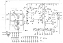
Comment on the 100db gain and 2H of -80db. Both the ShibaSoku generators and the analyzer use all descrete amplifers and same in osc...... both have what appears to be two gain stages in perhaps a compound arrangement to boost gain and total nfb.
It does not appear to me, yet, that there are any errors in the design of the 725D nor in using a 'sound card' on the 725D monitor port (a calibrated port). The measured levels have been cross-checked with other analyzers and get substantially same 2H and 3H data. I have shown these comparisons.
I have Not used a sound card/QA401 as sole instrument for anything below -100dB. I do have the Bench-Mark ADC and DAC2 to use instead of a sound card but from others measuremenets it is good for 22 bits. A notch filter will help a lot but I have moved on the the commercial analyzers/test equipment. So I cannot comment on what a notch and sound card accuracy might be like well below -100dbv.
THx-RNMarsh
Last edited:
Which is accurate to -140dbv.
A notch filter is not needed in my case. However, back a couple years i went that route and still have the passive, variable freq notch filter made by B&K 1607. useful on HP339A also.
Back to where we started, the -176dB broadband noise floor on that plot is wrong i.e. not physically possible. The others show -155dB or so a better answer.
There is an optimal solution in each case. When we want to measure extremely low distortions, then every part of system becomes a problem, and simplest solutions may be better. If you want to reduce fundamental to very low levels, then you may get problems with a complicated notch filter, and always will be a question, how are residual distortions of this active or tuneable device.
Samuel Groner has published extensively on the issues, resistors and capacitors at the -150dB level for 2V rms signals are readily available.
This is input amplifier (impedance convertor). Most of the gain change is done here.
All other gain stages are op amps.
Unlike the 339A and other analyzers the THD+N ratio calculation is done in the meter circuitry in DC. There is nothing done in the AC signal chain. Just gain change.
All other gain stages are op amps.
Unlike the 339A and other analyzers the THD+N ratio calculation is done in the meter circuitry in DC. There is nothing done in the AC signal chain. Just gain change.
Attachments
Last edited:
Back to where we started, the -176dB broadband noise floor on that plot is wrong i.e. not physically possible. The others show -155dB or so a better answer.
was that done on the VP7722A monitor port?
THx-RNMarsh
Back to where we started, the -176dB broadband noise floor on that plot is wrong i.e. not physically possible. The others show -155dB or so a better answer.
which plot, pls. i have made many on various instruments. I have also recently updated the 401 software to latest version with many fixes taken care of. scaling could be one of them... it seems to have erratic issues with that in early versions.
-RNM
Last edited:
BTW, the QA is nothing but a sound card in an instrument like wrapping.
My point too.
This is input amplifier (impedance convertor). Most of the gain change is done here.
All other gain stages are op amps.
Unlike the 339A and other analyzers the THD+N ratio calculation is done in the meter circuitry in DC. There is nothing done in the AC signal chain. Just gain change.
There is 1.5K in series with the input and feedback, so at a claimed 5nV noise you have already lost me. The input is 7nV noise best possible case.
Last edited:
Comment on the 100db gain and 2H of -80db. Both the ShibaSoku generators and the analyzer use all descrete amplifers and same in osc...... both have what appears to be two gain stages in perhaps a compound arrangement to boost gain and total nfb.
It does not appear to me, yet, that there are any errors in the design of the 725D nor in using a 'sound card' on the 725D monitor port (a calibrated port). The measured levels have been cross-checked with other analyzers and get substantially same 2H and 3H data. I have shown these comparisons.
I have Not used a sound card/QA401 as sole instrument for anything below -100dB. I do have the Bench-Mark ADC and DAC2 to use instead of a sound card but from others measuremenets it is good for 22 bits. A notch filter will help a lot but I have moved on the the commercial analyzers/test equipment. So I cannot comment on what a notch and sound card accuracy might be like well below -100dbv.
THx-RNMarsh
You also have an AP27xx. You can use the FFT without the notch routed before it.
This is lab instrument. If setup right will give an accurate reading.
I know the manual is pain but it will give a better answer.
Samuel Groner has published extensively on the issues, resistors and capacitors at the -150dB level for 2V rms signals are readily available.
I thought about the difference between an active or a tunable notch and the passive fixed twin T notch, which can't reduce the fundamental so much.
Just a though here. When I add the gains of the Shibasoku 725 I do bet better than 100dB.
However some of that gain is before the notch filters. The voltage going into the notch filter is well above the 0dB FS scale of the monitor output. This changes the SNR relative to the 0dBFS. There is not that much (100dB) gain after the notch filters. The minimum gain at the output of the impedance convertor is 6dB. For a 2.5Vrms input the output of the impedance convertor is 5Vrms. That's just the minimum. All of this is scaled back to 0dB at the monitor output. Doesn't that account for at least an additional 14dBV on the noise?
However some of that gain is before the notch filters. The voltage going into the notch filter is well above the 0dB FS scale of the monitor output. This changes the SNR relative to the 0dBFS. There is not that much (100dB) gain after the notch filters. The minimum gain at the output of the impedance convertor is 6dB. For a 2.5Vrms input the output of the impedance convertor is 5Vrms. That's just the minimum. All of this is scaled back to 0dB at the monitor output. Doesn't that account for at least an additional 14dBV on the noise?
Doesn't that account for at least an additional 14dBV on the noise?
The harmonics are referred to the input signal level, the broadband noise in the vicinity of the harmonics must also be they can not have different scaling except by the FFT order, windowing, etc. which you can compute.
I thought about the difference between an active or a tunable notch and the passive fixed twin T notch, which can't reduce the fundamental so much.
Actually a passive twin T has more than enough to eliminate any serious issues. Calibrating for the attenuation of the harmonics is an inconvenience but easily accomplished. Funny even that article from AP ignored potential scallop loss for the window they used. The devil is in the details.
http://dspguru.com/sites/dspguru/files/Scalloping Loss Compensation-Lyons.pdf
- Home
- Design & Build
- Equipment & Tools
- Low-distortion Audio-range Oscillator