If it is "probably OK" for LME49720, then you don't need to remove the GND plane (even if you use another opamp).
As the datasheet for the ADA4898, and other high speed parts, say not to have a ground plane over the inputs, it's best to remove it if using one of these parts.
I was hoping for a easier way, guess not!
Thanks
There is an easier way. Check out post 38 of this thread.
There is an easier way. Check out post 38 of this thread.
In reality it's a little bit more difficult with tps because they have big pad on the bottom... not only pins on sides!
In reality it's a little bit more difficult with tps because they have big pad on the bottom... not only pins on sides!
I might try this.
430°-800° /570°-1160° Interval Heat Gun with LED Temperature Settings
Hi.
Anyone willing to share their BOM to mouser or digikey? Please?
Regards
Ok, I can fill in my own order but what manufacturers and series are the best ones for different parts?
Regards
They also built it in 1 day which is slightly fast.
I was (one of) the first to get the boards, but nowhere did I say that I had built it - actually, I'm still gathering the parts.
I was not planning to use the onboard TPS regulator section anyway - there's a downstream header for +/-15V which I planned to use, with an external LM3x7 or similar regulator. So I probably would not have noticed the missing ground connection anyway. I'm guessing that Syllable did exactly the same thing, i.e. used an external regulator board.
BTW, I was the first to notice an error in the schematic (overlaid nets near the I2C isolator, which is apparently not an error on the layout).
Anyway, since there are people with working boards, it would appear that most of the errors can be worked around, even if they're a nuisance.
I just try my dac board with only tps regs plugged and I measured first, -12V and 2V at ouput... After looking the schematic, I don't believe myself to that huge error.
I have scratched soldermask and made contact and know I have +12V and -12V!
I would like to know the huge error on the schematic on the tps7a47 on which pin you made the contact. I used the same circuit in my DACs?
...it's just the beginning, and don't know what the futur reserve!
There is no error on the board whatsoever, I can assemble one dac for free if anyone interested in sending all parts to me with the board.
Have you tested it with AC input to the bridge rectifier section? I just checked the common node of C22 and C23, and it's floating (incorrectly) wrt to the ground plane, as stated by earlier posters. Without that ground, REG7 and REG8 regulators do not see rectified DC at their inputs, and are being operated out of spec - causing them to fail in many cases.
I'm not planning to use REG7 and REG8, but many others in the GB have paid for them, so you may want to at least offer spares to those whose regulators have failed.
Hi all,
Well, more bad news. I put together a new lm 317/337 psu set up for 1amp and had a nice listening session for about 20 minutes before some nasty distortion came thru the right channel. If I let the dac rest for an hour I can listen for another 20 minutes or so. Any one getting the same issue? Any ideas?
It is truly a shame how this project unfolded. The dac after only about maybe 2hours I've been able to listen, sounds very promising. It sounds very similar to my subbu es 9023, but IMO has maybe one degree more resolution and dynamics. I hope everyone has better luck. Cheers.
Hi all,
Well, more bad news. I put together a new lm 317/337 psu set up for 1amp and had a nice listening session for about 20 minutes before some nasty distortion came thru the right channel. If I let the dac rest for an hour I can listen for another 20 minutes or so. Any one getting the same issue? Any ideas?
It is truly a shame how this project unfolded. The dac after only about maybe 2hours I've been able to listen, sounds very promising. It sounds very similar to my subbu es 9023, but IMO has maybe one degree more resolution and dynamics. I hope everyone has better luck. Cheers.
What does the distortion sound like ... crackling? Whistling?
Is it losing lock to the s/pdif input?
Do any components get hot over time?
What does the distortion sound like ... crackling? Whistling?
Is it losing lock to the s/pdif input?
Do any components get hot over time?
Crackling and popping. No heat. How do I check the spdif lock?
Thanks. Regards.
There's a lock LED on the board. I've not built mine yet, but I'm assuming it should be lit when the DAC is locked onto the input. However, I'd expect both channels to distort if it starts losing lock.
It's worth checking all the supply voltages when it's distorting, particularly Avcc for both Left and Right.
Also double check your soldering, particularly on the DAC chip and the right channel of the output stage.
It's worth checking all the supply voltages when it's distorting, particularly Avcc for both Left and Right.
Also double check your soldering, particularly on the DAC chip and the right channel of the output stage.
Another thing, it's standard practice to connect a small (47r - 100r) resistor on the output of an opamp. It buffers it from capacitance, and helps maintain stability. This design doesn't have Rs on the output opamp though, so try fitting a couple (for left and right). Popping and crackling could well be opamp instability.
Another thing, it's standard practice to connect a small (47r - 100r) resistor on the output of an opamp. It buffers it from capacitance, and helps maintain stability. This design doesn't have Rs on the output opamp though, so try fitting a couple (for left and right). Popping and crackling could well be opamp instability.
Thanks, Spartacus. Where is best location on the board to place the resistors? Regards.
Thanks, Spartacus. Where is best location on the board to place the resistors? Regards.
You're welcome.
The outputs are pins 1 and 7 of IC12. You can either cut the tracks between these pins and the output, then solder a 100r where the track was, or solder the resistors between the output on the board and the output sockets. Probably best to use the second method while experimenting.
Last edited:
You're welcome.
The outputs are pins 1 and 7 of IC12. You can either cut the tracks between these pins and the output, then solder a 100r where the track was, or solder the resistors between the output on the board and the output sockets. Probably best to use the second method while experimenting.
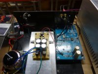
Spartacus, I attached two 75ohm resistors at the output, but still getting the crackling after about 15-20 minutes. I also added some shielded cable to inputs and outputs. I have to say the sound just keeps getting richer. If I can solve the distortion, this will be one incredible dac.
I disconnected the amps and cdp and measured voltages, but still did not see anything unusual. im in the process of inspecting solder joints. Any other ideas? Thanks. Cheers.
Attachments
Hi all,
Well, more bad news. I put together a new lm 317/337 psu set up for 1amp and had a nice listening session for about 20 minutes before some nasty distortion came thru the right channel. If I let the dac rest for an hour I can listen for another 20 minutes or so. Any one getting the same issue? Any ideas?
This is just pure conjecture, since I haven't assembled mine yet - but I'd suspect that the +5v SOT223 regulator that supplies all the other regulators is overheating. It has to drop +15v to +5v, and depending on the current drawn on the +5v, +3.3v and lower rails, could be drawing anywhere from 100 to 200 mA - which translates to 1 to 2W dissipation. Not much, but enough to make an SOT223 sizzle. A TO220 7805 or LM317 would have been a safer bet there.
Last edited:
- Status
- This old topic is closed. If you want to reopen this topic, contact a moderator using the "Report Post" button.
- Home
- Source & Line
- Digital Line Level
- Low cost ES9018 Dac - Builders Thread