Here is the real problem. If the amplifier failure mode is such that there is 80VDC on the output, the relay has to break 80VDC at about 10 amps. There isn't a relay made, that will fit in most any amp, that was designed to break DC. Check you're contact ratings. They're only rated for 24VDC. The relay will arc and weld under these conditions until the fuse blows. The fact that many amps have never had welded contacts upon failure says nothing about the relay. It just means the relay didn't have to break DC.
I couldn't resist this...
I fed 80 vdc into a TA7317 protection circuit to simulate an amplifier fault. It opened the relay. It will open the relay with less than 1 VDC also.
burnedfingers said:
I couldn't resist this...
I fed 80 vdc into a TA7317 protection circuit to simulate an amplifier fault. It opened the relay. It will open the relay with less than 1 VDC also.
I have been trying to point out that unless the INDUCTANCE in the circuit is considered, all these specs and tests are meaningless.
Of course speakers have inductance, but far far less than the industrial loads that relays may be specified for.
The failure mechanism will be worn / burnt / finally welded contacts depending on the sustainabilty of the arc.
My central heating boiler thermostat arcs for about 3 seconds every time it switches off. It has been doing that for 20 years ....
I have been trying to point out that unless the INDUCTANCE in the circuit is considered, all these specs and tests are meaningless.
Please explain to me why some of the more common protection circuits have been working very well for many years? The TA7317 protection IC works very well in a number of different amplifiers. It sees DC and trips....what more do you want anyway?
burnedfingers said:
Please explain to me why some of the more common protection circuits have been working very well for many years? The TA7317 protection IC works very well in a number of different amplifiers. It sees DC and trips....what more do you want anyway?
??
Who said they don't?? Not me!
I don't know what you mean!
the best relays to use are the "self cleaning" type, or better (but more expensive and politically incorrect) mercury wetted relays (one drawback is they MUST be mounted upright). mercury relays never burn contacts, but must be mounted properly, and have extreme disposal restrictions these days. they are usually hermetically sealed, so they don't pose a health risk with normal use. there used to be a lot of them available on the milsurp market.
You can get 40A mercury wetted relays.
I thought of using them at the speaker outputs, but they were "bigger than a grapefruit". In the end, I used (am still using) the shunt solution. And I only have 24V to switch in any case, which was within relay spec.
The best relay (in the signal path) is no relay.
Patrick
I thought of using them at the speaker outputs, but they were "bigger than a grapefruit". In the end, I used (am still using) the shunt solution. And I only have 24V to switch in any case, which was within relay spec.
The best relay (in the signal path) is no relay.
Patrick
i've seen some amps that use a relay to shut off the input stage of the amp by removing it's supply rails (actually it shunts the supply rails and "kills" them) as a form of protection. won't protect the speakers form a shorted output device, but protects the outputs from shorted speakers by killing the amp drive.
Just going slightly off the topic here, I know we all hate fuses in the speaker line, but has anyone tried the small "I/C circuit protectors" that are used as low voltage fuses. They are supposed to blow very quickly and could be soldered in circuit (no fuseholders) and placed within the NFB loop. I seem to remember them being available up to 6.3 amp. Suitable only for modest power outputs I know but they could provide a safeguard together with more convential protection. They could also possibly be used as rail fuses, or in the supply to the output devices. Just a thought ") . I also mentioned in previous post about a comparater type protection circuit. I have been having a play and hope to post a basic circuit outlining the idea. Initial results are good, the delay from the integrating network is eliminated. I also want to look into ways to turn off the relay quickly, possibly by applying a "short" via a transistor across the coil to speed up the turn off.
. I also mentioned in previous post about a comparater type protection circuit. I have been having a play and hope to post a basic circuit outlining the idea. Initial results are good, the delay from the integrating network is eliminated. I also want to look into ways to turn off the relay quickly, possibly by applying a "short" via a transistor across the coil to speed up the turn off.
Regards Karl
. I also mentioned in previous post about a comparater type protection circuit. I have been having a play and hope to post a basic circuit outlining the idea. Initial results are good, the delay from the integrating network is eliminated. I also want to look into ways to turn off the relay quickly, possibly by applying a "short" via a transistor across the coil to speed up the turn off. Regards Karl
peavey uses them as tweeter protection in their PA cabinets. all they do is increase in resistance when they trip, which makes the sound man crank up the highs more, which fries the protector, and the tweeter, and the crossover. they're more trouble than they're worth.
there's a circuit i've seen and will look for it to post, of a relay that gives 10sec turn-on delay, but operates lightning fast for offset, SOA detection and power failure. the trick for power loss trip is bypassing the turn-on delay circuit with a diode to provide instant capacitor discharge in the relay circuit if the power fails (i.e. the cap charges slowly at turn-on, but the charge gets dumped through a diode within microseconds if the power fails, making the turn-off time more dependent on the relay field collapsing than on the driver circuit.
there's a circuit i've seen and will look for it to post, of a relay that gives 10sec turn-on delay, but operates lightning fast for offset, SOA detection and power failure. the trick for power loss trip is bypassing the turn-on delay circuit with a diode to provide instant capacitor discharge in the relay circuit if the power fails (i.e. the cap charges slowly at turn-on, but the charge gets dumped through a diode within microseconds if the power fails, making the turn-off time more dependent on the relay field collapsing than on the driver circuit.
Yes, I know the one's your thinking of, seen them used in satellite receiver set top boxes as PSU short circuit protection, positors could'nt think of the name. The ones I was thinking of are non resetable and seem to have fallen out of favour a bit, we used to call them I/C protectors or circuit protectors. They were supposed to blow before damage was done to semiconductors, it did'nt always quite work out like that though Have a look at the link below for the sort of thing I meant.
Schurter
Regards Karl
Have a look at the link below for the sort of thing I meant.Schurter
Regards Karl
Burnedfingers,
From your posts elsewhere I know you prefer the TA7317 and with it's history I'm sure it works fine. It will trip the relay. My only question is, did you have a load on the amplifier when you tested it. My testing indicates that the relay, under load, will arc and possibly weld.
Cliff,
You've made your point on inductance. Can you point me to anything so that I can further understand this. When relay contacts are rated for resistive loads at 24VDC/250AC I don't understand how inductance is relevant.
Does anybody have access to Doug Self's article on output relays?
d3imlay said:Burnedfingers,
Cliff,
You've made your point on inductance. Can you point me to anything so that I can further understand this. When relay contacts are rated for resistive loads at 24VDC/250AC I don't understand how inductance is relevant.
I have looked myself and am also confused!
From basic theory, if there isn't any inductance then there isn't any arcing, because there is nothing storing energy to maintain it.
However a completely inductance free circuit is not possible, but nowhere in relay test specs is this quantified - most just say "resistive load". Are a few uH relevant? Doesn't sound probable to me.
I was hoping that someone could shed some light - there must be some other contact failure mechanism at large currents.
Cliff
actually tested
My reply is a bit late but might still be interesting as I've tested speaker protection in real world ...
The case: I've included Rod Elliot's speaker protection scheme (project 33 fig 1 and 3) in my attempts to build a JLH amp.
It saved my speakers about 6 times when the output transistors blew putting about 27 Volts on the speaker output. I admit that the Iq on my amp was only about 1 to 1.25 A, but still this should be enough to kill a tweeter (and no, I do not have a cap in series with the tweeter or any other protection).
I'm not sure which relais I put in series with the speakers (though they were expensive (about Euro 6 each)). I do not dare to remove them to compare things sound wise. If my amp ever gets stable (pfff, I'm getting tired of the thing), then I might consider to wire the relais to short the output as protection.
MArco
You folks can tell me if any of these various protection schemes have saved your speakers or not? Perhaps they do these days, but the last time I was in a position to have big amps, playing big speakers loud, no protection circuit could do anything other than prevent fires... seriously. Like closing the barn door after the critters are out...
My reply is a bit late but might still be interesting as I've tested speaker protection in real world ...
The case: I've included Rod Elliot's speaker protection scheme (project 33 fig 1 and 3) in my attempts to build a JLH amp.
It saved my speakers about 6 times when the output transistors blew putting about 27 Volts on the speaker output. I admit that the Iq on my amp was only about 1 to 1.25 A, but still this should be enough to kill a tweeter (and no, I do not have a cap in series with the tweeter or any other protection).
I'm not sure which relais I put in series with the speakers (though they were expensive (about Euro 6 each)). I do not dare to remove them to compare things sound wise. If my amp ever gets stable (pfff, I'm getting tired of the thing), then I might consider to wire the relais to short the output as protection.
MArco
Hi,
let's assume we strike an arc with a welding torch.
We do that by applying a high frequency strike voltage to start the arc or by scratching the surface and increasing the gap as the arc establishes, this is scratch start. The welding transformer provides the energy to maintain the arc (plasma flow) across the gap. If we increase the gap too far the arc extinguishes.
Now compare a relay passing DC current to a speaker or to a shorted terminal.
As the contacts start to open (equivalent to scratch start) the arc establishes and continues as long as there is sufficient voltage & current to maintain the plasma flow across the gap.
If the contacts have very wide separation, the arc should extinguish before reaching the rated voltage.
That unfortunately is the problem. Narrow separation to give low voltage switching ability and contacts that melt easily when the arc passes.
I suspect that an opening relay does not require much help in establishing the arc with or without inductance in the circuit.
What we really need are big contact gaps and contacts that don't suffer from melting and erosion until the arc has extinguished. I further suspect that these two characteristics are not conducive to good audio.
Now, could we parallel a high rating relay with a good sounding relay and use the good sound version to pass the audio signals. The sequencing of the contact opening and closing could use the high rating contacts to make the circuit and when needed to break it as well?
Quote
Burnedfingers,
From your posts elsewhere I know you prefer the TA7317 and with it's history I'm sure it works fine. It will trip the relay. My only question is, did you have a load on the amplifier when you tested it. My testing indicates that the relay, under load, will arc and possibly weld.
***************************************************
I simulated a defective amplifier by putting DC voltage on the relay contacts. I used the same voltage on the protection circuits so that the protection circuit would sample the same.
I pulsed the DC voltage to simulate a fault and never had a defect.
I have had amplifiers running a dummy load that have experienced a fault. Never had a welded contact.
In all the commercial amplifiers I have worked on and repaired and all the commercial systems I have worked on I have yet to see a relay with a welded set of contacts.
I'm not going to say that in some strange circumstance it might not happen. You also have to realize that engineers designing the various amplifiers over the years have also pondered the possibility of the same event. Altec Lansing's 9440 power amplifier used a magnet attached to the relay. I have even taken the magnet off the relay and still didn't experience any problems with the relay failing to unlatch.
With respect to DC ratings I am finding 30VDC ratings on contacts not 24.
I don't see where inductance is relevant. It might be of some small consideration IF the protection circuits didn't act as quickly as they do. Fortunately the modern protection circuits react very quickly minimizing any damage. I have yet to suffer the loss of a driver due to amplifier malfunction with a properly designed and working protection circuit. Forget the fuses and poly switches because they don't work.
At any rate the protection circuits such as the TA7317 seem to function properly so my personal opinion is why are we trying to re-invent the wheel. If something works then use it and if it isn't broken then don't try to fix it.
Hi,
I've seen a couple of sites state that the diode across the relay coil slows down the relay release time.
I have also seen that reducing the hold in current to near minimum reduces relay response times, i.e. allows it to release more quickly.
There are a couple (or maybe more) threads on this.
I've seen a couple of sites state that the diode across the relay coil slows down the relay release time.
I have also seen that reducing the hold in current to near minimum reduces relay response times, i.e. allows it to release more quickly.
There are a couple (or maybe more) threads on this.
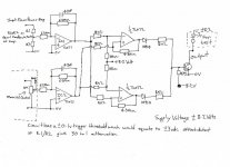
Way back at the start of this thread I mentioned I was looking into a way to overcome the inherent delay caused by the integrating network of most DC offset detection schemes and ways to speed up the turn off of the relay under fault conditions. I would appreciate comments (bad or good) on the following circuit idea. This is only at present an idea (and only the first part of the circuit-no relay drive and power on delay yet) but initial results are promising, the circuit is exactly as designed, and I know some of the component choices and supply rail values are a bit weird, but I know from experience the folly of making untested changes, even if they seem a good idea on paper at the time. One obvious complaint is the fact that it requires connection to the wiper of the volume control but it is via an extremely high impedance that works into a virtual earth, and I would be looking to "up" the value of the 6.8meg input resistors. The input has to be attenuated by a value equal to the feedback factor of the power amp and is set by R1 and R2 so that the inputs to the two OpAmps are identical, the 47pf cap forms a simple low pass filter, the two outputs then be fed to a comparator (TL072 at the moment) . A + or - 100mv dc offset triggers the output, so a 30 to 1 attenuation at the input would give + - 3 vdc detection of offset.
I would welcome any comments or opinions, if you think it's a non starter please say so.
Edit, Will probably be away till Friday.
Regards Karl
I would welcome any comments or opinions, if you think it's a non starter please say so.
Edit, Will probably be away till Friday.
Regards Karl
Attachments
- Status
- This old topic is closed. If you want to reopen this topic, contact a moderator using the "Report Post" button.
- Home
- Amplifiers
- Solid State
- Loudspeaker Relays