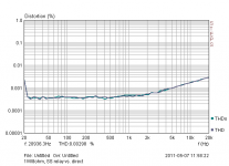
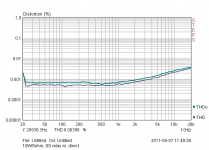
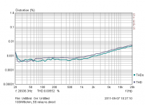
Look at attachments.. Do You mean, THD is ruined? Rdson is about 10mohm.Yes, the nonlinearity of Rds(on) will ruin THD long before Rds(on) itself ruins damping factor.
Attachments
Look at attachments.. Do You mean, THD is ruined? Rdson is about 10mohm.
Good point!
Looks good enough to me.
Quite interesting indeed!! And I'm reading this with great interest, with the intent to implement something like this on my leach amp that I'm currently working on.
I like this idea of placing that switch on the ground side of the speaker. And I would also like such switches on each rail and not use crowbars.
Yes, I think they are reasonably low in resistance and even compared with beefy and short cables, they may not have a noticeable impact.
What I have in mind is one switch on the ground side on the speaker as you describe, plus 2 switches, one on each rail, and then something on the primary side of the transformer to shut it down quickly.
I put together a power-on delay circuit, but perhaps I can improve on it and make it into a little more than that.
Good work!
Switching the ground return of the speaker is ok for muting only (this is what I do in my nx-Amplifier) but will not solve a short from the amplifier output to the chassis because you will be bypassing the SSLR. To solve this problem, put the SSLR between the amp output and the speaker +
Hi,
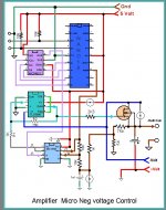
Just in case attached it is the schematic of my solid state relay I used in my LM3886 amplifier to switch ON/OFF the speakers by the micro processor. I installed them to provide the speaker ground in series with hall effect current sensor. If the current reached the shutdown setting it will remove the speaker ground. It is been running for about 8 months with not problems. It will close and open in about 65 micro seconds.
It is not longer in use in my new designed. I saved 4 mosfet transistors and few components
Attachments
Switching the ground return of the speaker is ok for muting only (this is what I do in my nx-Amplifier) but will not solve a short from the amplifier output to the chassis because you will be bypassing the SSLR. To solve this problem, put the SSLR between the amp output and the speaker +
How about in both locations? Those aren't really that expensive, although perhaps somewhat more than relays, they're worth putting in the most strategic places, and that also includes the rails.
They can be triggered together with the same signal. But I would want to be able to mute the output while I'm also muting the input, with the proper delay in the proper order.
How do you figure a short could happen with the chassis? (not including the plugging of badly wired cables) If a speakon plug is used and there is no way to cause shorts with those, if they're properly wired and used, then what causes are there for a short to chassis? The chassis should be tied to ground/earth anyway.
Hi,
Bonsai you have a point that I didn't think on that. I am reading the current to ground so if the speaker positive terminal it is ground I will not read the current. So I need to move the current sensor to read the current from the drivers to the terminal. In that way if there is a ground I will read the output current and the amplifier will be protected from the short. Good.
Bonsai you have a point that I didn't think on that. I am reading the current to ground so if the speaker positive terminal it is ground I will not read the current. So I need to move the current sensor to read the current from the drivers to the terminal. In that way if there is a ground I will read the output current and the amplifier will be protected from the short. Good.
Look at attachments.. Do You mean, THD is ruined? Rdson is about 10mohm.
What MOSFETs and how many in parallel did you use for this? My experiments gave about 0.003% extra THD at 100W into 4 ohms. Acceptable for me but Douglas Self would probably consider it "ruined".
I'm interested!
Hi spookydd
Nothing terribly advanced I should say.... for instance it's important to consider the arrangement of flyback diodes set(s), fuses, and reverse bias diodes between rail and ground (if fitted). In the event of an output transistor short, the huge instantaneous current may blow one rail fuse, then draw the current from ground through the reverse bias diode instead (generally a 1 or 2 amp 1n4xxx diode). If that diode goes open circuit (or it's not fitted, or is the other side of the fuse), the short may then drag one rail to below/above ground, thus drawing large fault current through one of the 2nd set of flyback diodes that may be fitted between relay and speaker (huge DC on speaker again, even if relay is open).
This is one reason I don't use the extra flyback diodes between relay and speaker.
Yes I went someway to designing this, using the highest current Mosfets I could find from Digikey. The issue for me is the huge fault current (available from PSU caps), that exist when the amp output stage shorts (or if you use them as crowbars rather than switches). Mosfets can fail open or short. In the end I didn't have the confidence to use this method, and reverted back to relay. If I was going to do it, I'd probably use two Mosfets in series, and probably have the relay as well for start up thumps.That's a good precaution. Have you considered using those mosfets as switches and do away with the output relays?
Absolutely. When I realised the protection circuit could be more complex than the amp I decided this wasn't the way forward. My protection is relatively simple; DC offset, RF detect, heatsink overtemp, gross overcurrent and rail-fail, driving a few logic gates, latch and a uP reset timer for start up delay. And a relay.I think this requires some extra command circuitry to handle the amp's power-up/down, so it gets done in the right order, and have an input muting done as well at the right moment, so there is no longer any signal when the amp actually is shut down.
More costs, always...
When one of the output transistor shorts, the fault current can be as high as the current generated by a crowbar, albeit reduced by the 2 x 0.22R resistors. This can easily and often does take out the other o/p transistor as well. A much higher current rated Mosfet used as a switch should survive this, but I'm not confident of this enough to risk my speakers. As stated above if i was to use Mosfets I would have relay as well, but then the whole idea seems a bit unworthwhile and overcomplicated for me. My rails are only 40V off load however. What is your basic amp configuration, is it particularly high power?A combination of switches in the amp's output and each rail should help, and if they are switches and not crowbars, then there is less potential stress caused, and perhaps the failing amp's outputs can be somewhat more limited to fewer damaged parts.
IRFB4110, 2pcs in series, not paralleled.What MOSFETs and how many in parallel did you use for this?
Those look great for amps with lower voltage rails. My test amp had +/-55V rails so I used some higher voltage parts with a somewhat higher Rds(on).
Reliability is a concern, but a mechanical relay can fail short too if it tries to break a hefty DC arc. I would be most worried about the solid-state relay making onto a shorted load. I used PVIs to drive it and they took the best part of a second to charge the huge gate capacitance. The FETs could dissipate a lot of power in that time.
The PVIs I used have a speedup circuit to turn off quickly, so breaking a DC fault shouldn't be a problem, assuming a second set of catch diodes on the speaker side.
When one of the output transistor shorts, the fault current can be as high as the current generated by a crowbar, albeit reduced by the 2 x 0.22R resistors.
And then those resistors can go up in smoke, and turn into fuses, if the power supply is strong enough.
This can easily and often does take out the other o/p transistor as well.
Well, maybe, maybe not. As many amp repair guys have stated, when repairing some of those amps such as the Soundcraftsmen for example, with those rails clamped. Then the damage is more limited and only few outputs get blown.
I was looking over some old schematics lately and when I saw what BGW did in their older models of the 500D and 750A (all 2N3773, 5 pairs for the 750). They use no VI or any other kind of limiters in the amp circuit, no output relay, no fuses on the output and rails, but they have an SCR across the rails, only one rail to rail, and a DC detect circuit to activate that.
A much higher current rated Mosfet used as a switch should survive this, but I'm not confident of this enough to risk my speakers.
I am now! I will alter my current design in progress to make use of those SSR.
Our friend Bonsai has done a great research job and writeup, and although I never liked mosfets myself too much before, I still am not interested in them for the amp itself, but those new PowerTrench with their speed, current handling and ruggedness are very interesting as a SSR.
I now want to look into having such switches on each side of the speaker output, plus I will remove the fuses I had first intended from the rails and add switches there too.
I want to implement an input mute with properly delayed output switch-on.
This will be a tad complicated, but looking at the much improved safety and comparing the costs with output relays and their shortcomings, this is worth the effort and cost I think. I am building a nice amp, and this will be only a first version, as I have plans for more.
My rails are only 40V off load however. What is your basic amp configuration, is it particularly high power?
With such lower rails, you might be fine with a good output relay, using that arrangement with the common turned to the speaker and the NC tied to ground. This seems to work quite nicely.
What I'm working on right now as my nice project is a Leach amp, and the rails will be about 61V. Then later I plan to make stronger versions with rails close to 80V.
The 80V rails will pose problem for those PowerTrench, as they only go to 150V max, so I will have to look further for higher voltage ones, but then those may not be quite as good as far as their Rdson and other characteristics.
I think I may be forced to consider an auxiliary power supply for the protection circuitry, because I'd like to be able to also switch off the transformer in case of fault, as the fault may cause the power to go out from the protection circuitry and cause some random state in the switches. I'm just trying to think ahead.
Looking at the prices for really good relays, comparing that to the cost of those mosfets and the few extra parts they require. I don't think it costs that much more really to go SSR and do away with a pending disaster. I wouldn't like to have done all the work, chosen a relay, and then when something happens it will end up with welded contacts and the damage will have happened anyway.
And then those resistors can go up in smoke, and turn into fuses, if the power supply is strong enough.
Yeah, although it might take some time, relative to how quickly speakers would survive large DC. Off subject slightly regarding bias resistors, which are usually wirewound and inductive, I changed mine to a 0.18R 5W metal plate, low inductive type, Digikey 0.18AFBK-ND. According to my spice sim this may reduce phase margin by more than 20 deg, assuming a low value wirewound might be 0.5uH or a lot higher. It's the only value they have so I bought a few before they go out of stock...
I guess a lot depends on how quickly the detector can shut off the power. I couldn't better about 60ms, without risk of it accidentally triggering. I'm not going to use any VI limiting either, can kill tweeters. Most of the commercial amp schematics I've seen don't use secondary fuses, either before or after rectifier, but I will probably use them for peace of mind. My amp at least according to spice, is likely to have a few volts dc on op during start up, so I think I will have to use relay on output.Well, maybe, maybe not. As many amp repair guys have stated, when repairing some of those amps such as the Soundcraftsmen for example, with those rails clamped. Then the damage is more limited and only few outputs get blown.
I was looking over some old schematics lately and when I saw what BGW did in their older models of the 500D and 750A (all 2N3773, 5 pairs for the 750). They use no VI or any other kind of limiters in the amp circuit, no output relay, no fuses on the output and rails, but they have an SCR across the rails, only one rail to rail, and a DC detect circuit to activate that.
Sounds good! I'd be interested to see the results of MOSFET power cut, should I ever want to build a higher power amp (assuming I ever finish the current one). How do you envisage the audio mute? I considered this, but didn't want to run audio through a chip, so I could only think of using a reed relay or similar, either as a switch, or more probably to short signal to gnd.I am now! I will alter my current design in progress to make use of those SSR.
Our friend Bonsai has done a great research job and writeup, and although I never liked mosfets myself too much before, I still am not interested in them for the amp itself, but those new PowerTrench with their speed, current handling and ruggedness are very interesting as a SSR.
I now want to look into having such switches on each side of the speaker output, plus I will remove the fuses I had first intended from the rails and add switches there too.
I want to implement an input mute with properly delayed output switch-on.
This will be a tad complicated, but looking at the much improved safety and comparing the costs with output relays and their shortcomings, this is worth the effort and cost I think. I am building a nice amp, and this will be only a first version, as I have plans for more.
Yeah I should be fine with the Omron high capacity relay for my voltages, likely fault current should be within the rated switching VA. I'm not going to use the NC terminal however, it shouldn't be required for my application. My project also started as a leach amp, but has morph into something else as I became more interested in reducing open loop distortion without adding gain stages, e.g. cascode VAS, and IPS constant voltage cascode. Also will be using jung type super reg for the IPS/VAS power...With such lower rails, you might be fine with a good output relay, using that arrangement with the common turned to the speaker and the NC tied to ground. This seems to work quite nicely.
What I'm working on right now as my nice project is a Leach amp, and the rails will be about 61V. Then later I plan to make stronger versions with rails close to 80V.
The 80V rails will pose problem for those PowerTrench, as they only go to 150V max, so I will have to look further for higher voltage ones, but then those may not be quite as good as far as their Rdson and other characteristics.
I think I may be forced to consider an auxiliary power supply for the protection circuitry, because I'd like to be able to also switch off the transformer in case of fault, as the fault may cause the power to go out from the protection circuitry and cause some random state in the switches. I'm just trying to think ahead.
Looking at the prices for really good relays, comparing that to the cost of those mosfets and the few extra parts they require. I don't think it costs that much more really to go SSR and do away with a pending disaster. I wouldn't like to have done all the work, chosen a relay, and then when something happens it will end up with welded contacts and the damage will have happened anyway.
Ask yourself if you want your amplifier's output running through a single point contact or not. I don't.
Do you want your amp running through 20ga wire or smaller?
There are wires used in relays...
Paralleled contacts are better than any single contact that I know of.
Jan's special relay sounds like some sort of improvement over standard contact arrangements.
Crosspoint and wiping contacts are clearly better, but have their own issues and are not terribly commonly available - or I've never seen them used in a power amp context...
Parallel contacts if you must use them.
Use the best contact arrangement & materials you can find for the job, and then parallel them.
Use larger contacts rated higher than you need.
Investigate the low power level behavior of the set up too...
Avoid relays if you can is my advice.
_-_-bear
A given resistance across the relay contacts, to limit the arcing 'peak'. It is the peaks that get you, not the averages. Thus, limit the peaks. choose a resistance value that is workable for the situation at hand, and put it across the relay pins that are relevant. When the relay is open, the resistance is negligible, and for the most part, so high, that no signal gets through. when the relay is closed, it is so high a value, that it matters not.
BUT..that resistor pair will limit arc peaks.
Properly handled (choosing the value), in long term use (analysis of examples in the field) of a given model of amp, it might notably increase the lifespan of the relays.
which are usually wirewound and inductive, I changed mine to a 0.18R 5W metal plate, low inductive type, Digikey 0.18AFBK-ND.
I started getting some of those MPC types, also non inductive and they seem to be able to handle some abuse. I've seen others that look the same, for example in an old pioneer hifi amp, although from a different manufacturer, something like RGC55. What I like about those is the fact that 2 of them are in the same package with a center tap, which is the way they are used most of the time, and this is nice when laying out the pcb.
It's the only value they have so I bought a few before they go out of stock...
You can find those MPCs easily, and they're not expensive like some other types (caddock)...
couldn't better about 60ms, without risk of it accidentally triggering. I'm not going to use any VI limiting either, can kill tweeters.
I don't like the side effects of the limiters, and I would really prefer not to use them, but until I am quite sure other methods can do the job right and allow not using limiters, I will continue using them for now. However this may soon change, depending on how effective the SSR are and if perhaps using them in more than one strategic location can be sufficient.
My amp at least according to spice, is likely to have a few volts dc on op during start up, so I think I will have to use relay on output.
An output mute relay is a must, if we want a silent turn-on for sure, but don't count on a relay for the worst DC faults then.
I have now decided the SSR with those TrenchPower mosfets are so much more efficient, fast and reliable than plain ordinary relays and far less likely to fail, I want to make use of them. And when I'm convinced, I may just forgo using limiters.
Sounds good! I'd be interested to see the results of MOSFET power cut, should I ever want to build a higher power amp (assuming I ever finish the current one).
On powerful amps, I think you have no choice, as the relays would need to be so much more beefy to handle the job right. The chances are such output relays failing are so high, and since there is a much better solution, then I think the choice is clear, if we want to have the best safety. (I wouldn't like to kill my JBLs)
How do you envisage the audio mute? I considered this, but didn't want to run audio through a chip, so I could only think of using a reed relay or similar, either as a switch, or more probably to short signal to gnd.
I've been giving this a lot of thoughts too. I too don't want to have the signal going through more chips if I don't have to, and I want to avoid adding more pollution.
There are solutions that may be a good compromise. I've been considering using those J111/J112 types, but not making the signal passing through, only using them as a shunt to ground or perhaps in some local feedback loop or something like that, to apply a mute but not be directly in the signal's path.
Switching the ground return of the speaker is ok for muting only (this is what I do in my nx-Amplifier) but will not solve a short from the amplifier output to the chassis because you will be bypassing the SSLR. To solve this problem, put the SSLR between the amp output and the speaker +
I'm thinking of putting a SSR switch on the ground side plus the amp's side, and then one on each rail. Perhaps the 2 switches on the output don't need to be handled by the same command signal and always switched at the same time if only for muting. But what's the difference anyway if we do switch them both together?
The switches on the rails can be simpler, with half the number of mosfets, but they're better if their command signal goes through an opto-coupler. Same with the SSR on the amp's output, which probably also should use an opto-coupler. This may not be needed for the one on the ground side.
The thing is, if we also add a fault switch on the primary side at the transformer, triggered by the same command signal, we'd have a rather safe shutdown on fault system.
As long as switches in the rails are not crowbars and they're between the amp and the filter caps, then perhaps we can still make use of the rails from the filter caps as the source of power for the protection circuitry.
Even after the transformer's primary has seen its power removed, we still have plenty of reserves in the filter caps, long enough to insure the protection circuit is still properly powered to handle the full shutdown of everything.
Now it's still necessary that a switch on a rail be a latching one, to prevent it from coming back on before full shutdown.
There must be a simple way, not using microcontrollers or such complex circuits that require an extra psu, to handle the command signals and do the protection sensing, all using discreet components not requiring an extra psu.
My approach was to put the SSR in series with the speaker output and drive it using the exact same anti-thump and protection circuit that I used with mechanical relays before.
Rod Elliott sums up the different ways of driving SSRs here.
ESP - MOSFET Solid State Relays
I used the PVI1050 which has the turn-off JFET built in. It is an expensive part by consumer electronic standards, but a bargain by audiophile standards.
Rod Elliott sums up the different ways of driving SSRs here.
ESP - MOSFET Solid State Relays
I used the PVI1050 which has the turn-off JFET built in. It is an expensive part by consumer electronic standards, but a bargain by audiophile standards.
- Status
- This old topic is closed. If you want to reopen this topic, contact a moderator using the "Report Post" button.
- Home
- Amplifiers
- Solid State
- Loudspeaker Relays