These points are all good food for thought.
A crowbar (either relay or Triac) is not out of the question. If the amp has been designed to properly withstand a short, the crowbar action will not add damage, and will do a good job of protecting the loudspeaker (which always must be the top priority). If the amp output has gone big DC due to a shorted output transistor, the crowbar action won't do much more damage anyway.
I advocate Zobels on BOTH sides of the RL network. The Zobel on the amplifier side is desirable for HF stability of the output stage. Ideally, it is close to the output stage, with very low wiring inductance in between. The Zobel on the loudspeaker side is best right at the speaker terminals, and can help to damp out behaviors that will allow EMI ingress. If an output relay opens, it certainly doesn't hurt to have the second Zobel there to absorb stored energy in the loudspeaker drivers and crossovers.
Cheers,
Bob
Hi everybody,
Right now I am working in few problems and solutions already mentioned here.
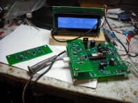
I have a prototype that will constantly monitor the AC and if one of the cycle it is lost the micro will turn off the amplifier. Also it will not allow to turn on again until it is turn off/on. This will prevent the amplifiers turn on in case of AC power outages. Also I eliminate the speaker output relays and control it by shutting down the rails voltages immediately. I am controlling and monitoring the rails voltage and adjust them accordingly of the voltage set point. This will eliminate the output relays. Everything explained above it is running in a prototype. When the amplifier it is turn on/off the rails voltages are slowly ramp up/down and the voltage it is control and monitor by the micro. Everything it is controller by a micro. Attached it is a picture of the running prototype. Also the speakers are turn on/off by monitoring the current using a hall effect current sensor. If the current it is reach the set point it will shutoff the rails voltages to protect the speakers. Suggestions are welcome.
Right now I am working in few problems and solutions already mentioned here.
I have a prototype that will constantly monitor the AC and if one of the cycle it is lost the micro will turn off the amplifier. Also it will not allow to turn on again until it is turn off/on. This will prevent the amplifiers turn on in case of AC power outages. Also I eliminate the speaker output relays and control it by shutting down the rails voltages immediately. I am controlling and monitoring the rails voltage and adjust them accordingly of the voltage set point. This will eliminate the output relays. Everything explained above it is running in a prototype. When the amplifier it is turn on/off the rails voltages are slowly ramp up/down and the voltage it is control and monitor by the micro. Everything it is controller by a micro. Attached it is a picture of the running prototype. Also the speakers are turn on/off by monitoring the current using a hall effect current sensor. If the current it is reach the set point it will shutoff the rails voltages to protect the speakers. Suggestions are welcome.
Attachments
A crowbar (either relay or Triac) is not out of the question. If the amp has been designed to properly withstand a short, the crowbar action will not add damage, and will do a good job of protecting the loudspeaker (which always must be the top priority). If the amp output has gone big DC due to a shorted output transistor, the crowbar action won't do much more damage anyway.
It's true that once something went wrong in the output stages of the amp itself, there isn't that much more damage to be done by a crowbar, although still, it may get worse. However I think a more sensible thing to do is put crowbars on the psu rails, perhaps the best place (before the amp) is after the rail fuses, so the crowbar can blow them. I would be more in favor of this type of solution, but nothing prevents anyone from putting crowbars in both places and have them work together.
The crowbars can all be triggered by the same protection circuit, and now that I think of it, those protection circuits better not use the rails for their own power.
I am thinking about using mosfets with an opto-coupler to command them, which should be very easy to handle from the protection circuit point of view and simple to implement. The same protection output signal can trigger crowbars on the amp's output, 2 crowbars on the psu rails and perhaps some other type of triac/scr even earlier in the psu, maybe even before the transformer, to bring down the psu by more than one mean. I think there must be an easy way to trigger the psu off at the level of the power-on delay circuit.
I advocate Zobels on BOTH sides of the RL network. The Zobel on the amplifier side is desirable for HF stability of the output stage. Ideally, it is close to the output stage, with very low wiring inductance in between. The Zobel on the loudspeaker side is best right at the speaker terminals, and can help to damp out behaviors that will allow EMI ingress. If an output relay opens, it certainly doesn't hurt to have the second Zobel there to absorb stored energy in the loudspeaker drivers and crossovers.
That seems like a sensible thing to do and I'm going to see how to implement this as well.
Now thinking about the output relays, the distortion they add, plus their effect on the damping factor. I think having the feedback tapping on the far side of that relay might be a good thing to do so the extra distortion would get reduced. However when the relay switches off, then there is no feedback loop any more, so perhaps a double feedback loop needs to be put in place, with one tap as usual on the amp's output, plus an other on the far side of that relay switch to include it in the loop. This obviously needs to be done right.
If we implement the output relay as a SPDT with the speaker line on its common and the NC contact going to ground, the extra feedback loop would tap on the switch common/speaker line and when the relay drops, that feedback then goes to ground, and there must be an "inner" feedback from the amp's output to keep it closed loop. I would like to know the actual effect of such a double feedback loop.
One of the ideas that I wanted to work on with the NC contact grounded, is to insert a resistor there and have some type of sensor to detect a short on the speaker line through that relay conact on power-up, so the protection circuit would not activate the output relay and connect the amp to a shorted line. Eventually this can detect automatically if/when the short goes away, and perhaps with some extra delay added, then activate the output relay when the path is clear.
I think a combination of several such protections and sensor are a better way to make a robust amp.
I have a prototype that will constantly monitor the AC and if one of the cycle it is lost the micro will turn off the amplifier. Also it will not allow to turn on again until it is turn off/on. This will prevent the amplifiers turn on in case of AC power outages.
This sounds interesting, but I would not want the amp to go off just because one cycle or half cycle is missed. There are sometimes micro-brownouts that happen and that doesn't mean the power is really out. Plus this could also be triggered by some other devices nearby on the power lines that cause severe transients. I've seen some laser printers doing uggly things like this, sometimes photocopiers or some other types of motor based of big transformer based devices, can cause at least momentary dips that could be misinterpreted as power outages.
Also I eliminate the speaker output relays and control it by shutting down the rails voltages immediately.
Eliminating the output relay and avoid a crowbar on the output would also be nice, however if you protect from the rails, even with a fast shutdown via a crowbar or something of that nature, if something bad happened in the amp's output stage and a shorted device sends DC to the speaker, even for a short burst before the rails are brought down, this may still be dangerous to speakers. The big woofers may survive such DC burst if short, but what about tweeters?
above it is running in a prototype. When the amplifier it is turn on/off the rails voltages are slowly ramp up/down and the voltage it is control and monitor by
How are the rails controlled and shut down?
the micro. Everything it is controller by a micro. Attached it is a picture of the running prototype. Also the speakers are turn on/off by monitoring the current using a hall effect current sensor. If the current it is reach the set point it will shutoff the rails voltages to protect the speakers. Suggestions are welcome.
I wouldn't go to the extent of using a micro for a protection system, the micro could cost almost as much as the amp's circuit, especially if there is a display, keyboard and whatever.
This can be done much simpler with discreet components, and at a much lower cost. I guess it depends on what use the amp is destined for.
Avoiding the use of output relays has its advantages. No added distortion or extra resistance in the path to the speaker to reduce the damping factor.
As long as other, multiple precautions are taken somewhere else, especially on the rails to prevent speaker damage in case of amp output failure, I'd go for that.
I even contemplated at some time having the amp located right in the speaker's case. Being used in a multi-amp setup, with one amp per speaker, and the shortest possible length of cabling between the amp's output and the speaker. I considered having a feedback loop sensor going all the way to the speaker's connection, so all wiring between the amp's output and the speaker itself would be included inside the feedback loop.
This would make a really good situation, with no output relay and very short cabling.
Some have even added sensors on the speakers to use their motion to compensate and make corrections, but then we're getting into some serious complexity here.
This sounds interesting, but I would not want the amp to go off just because one cycle or half cycle is missed.
A missed half cycle is worst case for transformer inrush current.
A toroidal will typically saturate the core and the resultant current can exceed normal by 1000% or more.
Eliminating the output relay and avoid a crowbar on the output would also be nice, however if you protect from the rails, even with a fast shutdown via a crowbar or something of that nature, if something bad happened in the amp's output stage and a shorted device sends DC to the speaker, even for a short burst before the rails are brought down, this may still be dangerous to speakers. The big woofers may survive such DC burst if short, but what about tweeters?
How are the rails controlled and shut down?
Trench FETs can shut the rails down in a few microseconds.
Protect the speakers AND the transistors.
It's a really nice idea.
I wouldn't go to the extent of using a micro for a protection system, the micro could cost almost as much as the amp's circuit, especially if there is a display, keyboard and whatever.
This can be done much simpler with discreet components, and at a much lower cost. I guess it depends on what use the amp is destined for.
Tauroo uses a microCONTROLLER chip. These are a few bucks.
Cheaper than discrete and probably actually simpler, once you are tooled up for them.
He also uses it for inrush current control.
Once you have the microcontroller the extra functionality is almost free.
Best wishes
David
Last edited:
A missed half cycle is worst case for transformer inrush current.
A toroidal will typically saturate the core and the resultant current can exceed normal by 1000% or more.
That may be true at the time of power-up, but then once established and the amp is functioning, what's the worst that could happen then? I wouldn't want the amp to go off in the middle of being used just because of some glitch on the power lines.
Trench FETs can shut the rails down in a few microseconds.
Protect the speakers AND the transistors.
It's a really nice idea.
Sounds perfect, and we could do away with an output relay.
Where can we find useful info on this?
What kind of current intensity can they handle? How are they triggered?
Tauroo uses a microCONTROLLER chip. These are a few bucks.
Cheaper than discrete and probably actually simpler, once you are tooled up for them.
Well, arduino doesn't cost much for example and probably could do the job as well, but then it requires an extra power supply and a separate pcb just for it, plus perhaps another for some peripherals...
Do you know any examples that can be looked at on the web?
He also uses it for inrush current control.
Once you have the microcontroller the extra functionality is almost free.
Quite true! Once the extra pcb and psu in there, why not maximize its usage?!
I'm trying as much as possible not to need an extra psu and transformer.
Making use of the main amp psu, using all discreet. Even a vu-meter getting its power from the rails as well. If a very good setup can be used, with advantages such as avoiding output relays, I would consider adding the extra psu that is 100% separate from the amp's.
That may be true at the time of power-up, but then once established and the amp is functioning, what's the worst that could happen then?
The inrush can blow the mains breaker and take down the circuit.
Only inconvenient for a home, I believe half cycle protection is required for medical equipment, for obvious reasons.
Sounds perfect, and we could do away with an output relay.
Where can we find useful info on this?
Search this forum for "trench FET" and "protection" or similar.
Lots of info.
Do you know any examples that can be looked at on the web?
Search this forum for previous post by Tauro
Best wishes
David
I am thinking about using mosfets with an opto-coupler to command them, which should be very easy to handle from the protection circuit point of view and simple to implement. The same protection output signal can trigger crowbars on the amp's output, 2 crowbars on the psu rails and perhaps some other type of triac/scr even earlier in the psu, maybe even before the transformer, to bring down the psu by more than one mean. I think there must be an easy way to trigger the psu off at the level of the power-on delay circuit.
Now thinking about the output relays, the distortion they add, plus their effect on the damping factor. I think having the feedback tapping on the far side of that relay might be a good thing to do so the extra distortion would get reduced. However when the relay switches off, then there is no feedback loop any more, so perhaps a double feedback loop needs to be put in place, with one tap as usual on the amp's output, plus an other on the far side of that relay switch to include it in the loop. This obviously needs to be done right.
If we implement the output relay as a SPDT with the speaker line on its common and the NC contact going to ground, the extra feedback loop would tap on the switch common/speaker line and when the relay drops, that feedback then goes to ground, and there must be an "inner" feedback from the amp's output to keep it closed loop. I would like to know the actual effect of such a double feedback loop.
One of the ideas that I wanted to work on with the NC contact grounded, is to insert a resistor there and have some type of sensor to detect a short on the speaker line through that relay conact on power-up, so the protection circuit would not activate the output relay and connect the amp to a shorted line. Eventually this can detect automatically if/when the short goes away, and perhaps with some extra delay added, then activate the output relay when the path is clear.
I think a combination of several such protections and sensor are a better way to make a robust amp.
Yes, MOSFETs indeed are useful in the rails as an electronic circuit breaker. Moreover, if they are used in a source-follower arrangement, they can be configured as capacitance multipliers in the rails, pretty much killing PS ripple and noise to the whole output stage - at least until one runs out of headroom. This approach generally requires low-current boosted rails to provide the needed hard turn-on voltage for the gates in this common collector arrangement.
Taking the feedback after the speaker relay while keeping the feedback loop closed when the relay is open is covered in my book, but I don't have it in front of me. Keeping the loop closed under all conditions is very important.
Cheers,
Bob
I have a small write- up on this subject here Solid State Loudspeaker Relay and here Solid State Relay with PCB Layout.
I would not lose any sleep over the MOSFET Rdson ruining damping factor. Modern 100 V Trench devices for example offer Rdson figures of around 4 mOhm, while 150 V devices are well under 10 mOhm. These numbers are swamped by the speaker cable resistance.
I would not lose any sleep over the MOSFET Rdson ruining damping factor. Modern 100 V Trench devices for example offer Rdson figures of around 4 mOhm, while 150 V devices are well under 10 mOhm. These numbers are swamped by the speaker cable resistance.
Indeed!No thread is ever totally dead! We can resurrect it!")
It's been a while since I posted this, and have done a significant amount of simulation and analysis on this and other fault issues, so my implementation has now changedI'm also doing design right now and pondering on the same things.
I believe the first step should be to thoroughly analyse the design for fault modes, and in the instance of output-at-rail-voltage, ascertain what the likely fault current and voltage across relay would be.I was just considering changing my current design to do as suggested with double throw switches tied to ground. That would be a better configuration.
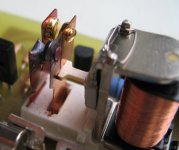
In my design the output stage rails are at 40V off-load, however taking into consideration transformer regulation (4%), reservoir capacitance (10000uF) and all impedances in the path, the power rails sag considerably in less than 50ms, to something under 30V, with a fault current around 6-7A. My protection circuit operates in just about 70ms so relay will not break until rails have sagged. Using the Omron G2R-1-E-DC24 this falls under the switching VA curve for inductive load. Therefore in my design I think there is little risk of severe contact arcing and have reverted to a traditional configuration with relay NC contact disconnected.
The problem arises when using higher rail voltages and/or transformer with lower regulation (or higher VA). You have double whammy of increased voltage and current.
Yes this is what I intended, but probably didn't word very well. However the issue with this configuration is that a smaller/briefer arc, that would perhaps not normally cause an issue, would potentially turn into a catastrophic arc, i.e. a direct short from rail to ground, potentially destroying output stage components and the relay. This could happen for instance if you turned the amp off whilst audio is being played through it.That's not how I saw it. The switches are turned around with their common going to the speaker and not to the amp's output. So when the relay releases, it's the speaker that is connected to ground and not the amp's output. At least that's how I understand it, and it makes sense to me, as the inductance in the speaker can cause the arc to remain longer and shorting it to ground can only stop this quicker.
I don't think the spreakers are in danger that way and the amp gets an open output and is no longer hooked to the speakers.
Relay manufacturers do not recommend this configuration, one datasheet I have seen specifically states not to connect relay in this way. However instead of connecting NC direct to gnd - with a resistor in the path e.g. 3R this would hopefully not be such an issue, and if using higher voltages (much above 40v) this could be a simple solution to ensuring there is adequate fault current to blow a (fast) fuse quickly.
I can't picture the arrangement as such, but I consider protecting the speakers to be top priority (i.e. DC offset & RF), as well as fire/electric shock prevention. I do have a simple detector across the 0R22 resistors for short circuit/gross overcurrent, not exactly SOA protection, and this operates the same relay on detection.There is only so much energy stored in that speaker's inductance, it will stop more quickly that way than if still arcing from the amp's output I think.
But there is one possible use for that extra resistor to ground in that place, it's to sense a short on the speaker line, so that can be used by the protection circuit to decide if it's closing that relay or not, so at least on power-up the shorted speaker line can be detected before the amp sees it, and it will never see it if this is handled properly.
I've been thinking about such a detection too...
Agreed but also see comments under next point.There is one good reason to have that zobel wired right at the amp's output and before a protection relay. When the output relay has opened, the only load the amp can see is that zobel. Better that than no load...
Flyback diodes - yes I have moved these and mounted them directly between collector(power rails) and emitter terminals on power transistors (this aids PCB layout). I am a little cramped on space (read budget) and don't bother with a second pair of flyback diodes on the other side of relays, or another zobel (one should really be sufficient).One thing I would do: move the flyback diodes to the other side of the relay, where they belong, on the amp's output and leave the speaker on its relay common alone.
I've seen both, the zobel on either side of the output R//L. I wonder what's the best position. Many people say leave it off the main pcb and put it on the output terminals on the case. But then it's far away from the amp, most likely way after any eventual protection relay and if the amp gets unhooked (by the relay), then it has no load left. Perhaps it doesn't hurt to have more than one zobel. Or I've even see amps (crown) with only a cap on the output, not a zobel.
I believe the key point for zobel arrangement is the PCB layout and grounding. On the Leach amp, the zobel was placed after the L/R, directly across speaker output terminals, as there were issues with oscillation with it amp-side of L/R. On some amps the zobel is placed before the L/R but there is a 50-100nF cap between 'zobel ground' and 'speaker ground'. On my design I will route the speaker ground from the output socket to the pcb, and then (using large pcb holes very close together) the speaker return from PCB to star ground at reservoir caps. The zobel, and small value 100uF local caps, will ground at the same point where the speaker ground leads 'meet' on the pcb, thus ensuring solid grounding for the power output section. I will probably also have a 100nF ceramic or two, connecting this speaker/power ground to ground for the preceding sections (must not be connected DC to prevent ground loop).
I've also seen amps where there is no zobel or is capacitor only. Personally I would stick to the traditional arrangement with 100nF/3-5R as it is tried and tested.
I believe relay protection is the best form, as it also prevents start up thumps. I have not been able to detect any reduction in audio quality with using a relay (the G2R-1-E-DC24 is very tried and tested). My concern with alternative methods such as mosfets in the power lines, is that complexity can be increased, and thus the risk of protection circuit failure. Also e.g. when output stage transistors short, the instantaneous currrent flow can be huge, and this can cause Mosfets to fail immediately short circuit mode.
Hope this is of some help
Last edited:
Attachments
Yes, MOSFETs indeed are useful in the rails as an electronic circuit breaker.
I am considering using those as a relay switch on the output and then pondering which would be best for the rails, either as a crowbar or a switch. But I would lean more towards the switch than the crowbar, as I think that is a really radical measure that can cause more issues when trying to deal with one.
A switch in the output should take care of the speakers's safety, then switches in both rails would prevent much damage in the amp's circuits, if they're fast enough and as long as they're between the filter caps and the amp.
Besides, using mosfets as switches makes for rather low dissipation in them, most likely much less than when used as crowbars. Furthermore, used as switches, they remove the power from the circuits, prevent some damage and while avoiding the extreme stress caused by crowbars.
I was just looking over some old schematics from BGW, and one of their old quasi 2N3773 amp, has no protection circuits in the amp itself (no limiters) and no output relay, but it does have an SCR with a resistor in series across the rails, from rail to rail and not one on each.
Moreover, if they are used in a source-follower arrangement, they can be configured as capacitance multipliers in the rails, pretty much killing PS ripple and noise to the whole output stage - at least until one runs out of headroom. This approach generally requires low-current boosted rails to provide the needed hard turn-on voltage for the gates in this common collector arrangement.
This is intriguing, as it could improve the basic psu without resorting to regulation.
Taking the feedback after the speaker relay while keeping the feedback loop closed when the relay is open is covered in my book, but I don't have it in front of me. Keeping the loop closed under all conditions is very important.
That was my point. When the relay is open, then the amp has no feedback, unless perhaps if the relay's common is on the speaker side and we ground the NC contact, then the feedback loop on that end is at ground, but then only the amp's input stage has a feedback and nothing else.
I've seen some doing this with 2 feedback loops, with one on the far side of the relay and the other on the amp's output as usual. Obviously this needs proper calculation.
I have a small write- up on this subject here Solid State Loudspeaker Relay and here Solid State Relay with PCB Layout.
Quite interesting indeed!! And I'm reading this with great interest, with the intent to implement something like this on my leach amp that I'm currently working on.
I like this idea of placing that switch on the ground side of the speaker. And I would also like such switches on each rail and not use crowbars.
I would not lose any sleep over the MOSFET Rdson ruining damping factor. Modern 100 V Trench devices for example offer Rdson figures of around 4 mOhm, while 150 V devices are well under 10 mOhm. These numbers are swamped by the speaker cable resistance.
Yes, I think they are reasonably low in resistance and even compared with beefy and short cables, they may not have a noticeable impact.
What I have in mind is one switch on the ground side on the speaker as you describe, plus 2 switches, one on each rail, and then something on the primary side of the transformer to shut it down quickly.
I put together a power-on delay circuit, but perhaps I can improve on it and make it into a little more than that.
Good work!
It's been a while since I posted this, and have done a significant amount of simulation and analysis on this and other fault issues, so my implementation has now changed
I'm interested!
I believe the first step should be to thoroughly analyse the design for fault modes, and in the instance of output-at-rail-voltage, ascertain what the likely fault current and voltage across relay would be.
That's a good precaution. Have you considered using those mosfets as switches and do away with the output relays?
components and the relay. This could happen for instance if you turned the amp off whilst audio is being played through it.
I think this requires some extra command circuitry to handle the amp's power-up/down, so it gets done in the right order, and have an input muting done as well at the right moment, so there is no longer any signal when the amp actually is shut down.
More costs, always...
(the G2R-1-E-DC24 is very tried and tested). My concern with alternative methods such as mosfets in the power lines, is that complexity can be increased, and thus the risk of protection circuit failure. Also e.g. when output stage transistors short, the instantaneous currrent flow can be huge, and this can cause Mosfets to fail immediately short circuit mode.
A combination of switches in the amp's output and each rail should help, and if they are switches and not crowbars, then there is less potential stress caused, and perhaps the failing amp's outputs can be somewhat more limited to fewer damaged parts.
Hi,
Sorry for no answer the questions I was working in my prototype with a display bug.
I forget to mentioned but I also slowly ramp the AC to the transformer at zero crossing when the amplifier it is turn ON/OFF. This will prevent the inrush current at the turn ON/OFF. I been using this for at least 8 months in my amplifier with no problems.
I am using the ACS712- 5 amps for the speaker current monitoring. You can buy it as 5,12,20,30,50 ,100 amps.
What I do to the rails voltage it is to monitor the current and if it reached the tripping set point immediately I shut off the mosfet gate. Attached it is block diagram of the voltage control. I can control the rails voltage up to 140 volts single polarity or +/- 70 volts dual polarity.
I am using the Basic micro nano28 that it is $10.00 and it is programming using simple basics.
- Status
- This old topic is closed. If you want to reopen this topic, contact a moderator using the "Report Post" button.
- Home
- Amplifiers
- Solid State
- Loudspeaker Relays