did you saw my attached schematic ?
i am not trying to find fault but to clear my doubt .
i check all components and track and everything is fine ,and i know that
their are many people who made this amp successfully. but what about schematic is it wrong or not ?
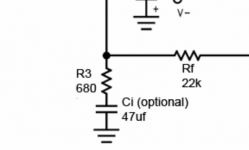
are you using the same pcb layout that is attached in page 1 or you draw your own pcb layout base on the schematic? if you use the attached pcb layout then the position of C4 and R3 is already fixed but in the schematic it is reversed.
you should also check your IC chip if it still good or already busted.
attached image the position of R3 and C4(Ci in the attached image)
Attachments
Last edited:
Apex is wrong.hello drahcir
please check the schematic this shows c4 +ve terminal conected to pin no 9 of ic LM 3886
The C3 is shown connected to -IN pin.
Do not connect any capacitor to -IN Pin except if you are a designer applying compensation.
Pin7 is shown grounded.
To unmute you must supply -ve current into pin7.
One cannot do that if it is connected to Signal Ground.
Signal Ground is shown connected to Power Ground.
It works but introduces room for error in output quality.
Last edited:
A power amplifier generally has no volume adjustment.
The volume adjustment is generally located at the output of the Source feeding the Power Amplifier.
Some will fit a sensitivity pot at the input of a Power Amplifier to allow precise setting of levels. This is a vol pot with restricted range and often linear track instead of audio law.
The volume adjustment is generally located at the output of the Source feeding the Power Amplifier.
Some will fit a sensitivity pot at the input of a Power Amplifier to allow precise setting of levels. This is a vol pot with restricted range and often linear track instead of audio law.
Apex is wrong................
did you read my post?amp works even when i disconnect -ve rail and mute again when -ve rail connected .why is that is my chip got busted ?
did you read my post?
Hello AndrewT
I want to ask simple question the value of C4 is 10uf/16v and C1 & C8 is
220 nf/63v mks .If I use same value cap but higher voltage rating is it make
any difference . because for C4 i am using 10uf/50v and C1& C8 220nf /100v
mks,I am not getting exact volt rating cap .
Using higher voltage rating doesn't affect anything if the caps are of same brand and build it's probably better to use higher voltage rating, lower voltage rating will cause problems not higher rating, probably the cost with increase, it is of no use if a 16v rating cap is working fine.
Using higher voltage rating doesn't affect anything if the caps are of same brand and build it's probably better to use higher voltage rating, lower voltage rating will cause problems not higher rating, probably the cost with increase, it is of no use if a 16v rating cap is working fine.
The brand and build also matter very little.
Make sure your caps are at least a minimum voltage of 125% of the max rail voltage of the power supply. If the power supply is 20v each side then the caps should be a minimum of 25v or else they will explode.
In many cases the capacitance can also be different. If the schematics call for 220uf and you only have 1000uf then try it. If you only have 100uf then just parallel two. Using less capacitance will usually only result in a noisier power supply.
Uriah
hello
can anyone help me why my amp not working . i build new pcb again as on first page layout and replace with new LM 3886 but problem of mute remain same ,I check output it about 1to 2v but when i turn off power supply it show deflection rise in voltage about 15 to 16v .
can anyone help me why my amp not working . i build new pcb again as on first page layout and replace with new LM 3886 but problem of mute remain same ,I check output it about 1to 2v but when i turn off power supply it show deflection rise in voltage about 15 to 16v .
I am sorry but you have not provided anyone with much info. My only guess at this moment is that you put the zener diode backward. I am not in a position to check email every day as I am working on my house and searching for a new one but I will try to help and hopefully someone else can help as well. However, with not even a picture you wont get far. A picture needs to be close up, in focus and an appropriate size to post on this forum.
I am sorry but you have not provided anyone with much info. My only guess at this moment is that you put the zener diode backward. I am not in a position to check email every day as I am working on my house and searching for a new one but I will try to help and hopefully someone else can help as well. However, with not even a picture you wont get far. A picture needs to be close up, in focus and an appropriate size to post on this forum.
Hello udailey
I am posting pic of amp
Attachments
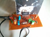
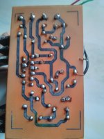
My lm3886 chips have light grey writing on them so its possibly a fake. component placement looks correct. My concern in the solder spatter. This is everywhere. Especially near pins 1-6 and there is a bug burn mark in the board near 2,4,6. Spattered solder causes arcing/shorting and will kill or temporarily disable an amp. Thats my guess. I always use an awl to scratch away any spatter between traces on my homemade boards.
Nail polish remover often has oil in it and is rather expensive. Just go to any paint or hardware store and get a bottle of acetone. Clean the toner/ink off the board with that before soldering. Either cover the board with spray flux or solder it within a few hours of cleaning, otherwise the copper will oxidize and make soldering harder.
You also need supply decoupling where the power enters the board. 1000 uF where the power comes into the board, 22 uF || 1 uF X7R ceramic right on the pins.
I don't see the point of the two diodes.
~Tom
You also need supply decoupling where the power enters the board. 1000 uF where the power comes into the board, 22 uF || 1 uF X7R ceramic right on the pins.
I don't see the point of the two diodes.
~Tom
Last edited:
The zener allows the amp to unmute at the zener voltage avoiding turn on thump.
You could achieve the same result by choosing Rmute appropriately.
~Tom
- Home
- Amplifiers
- Chip Amps
- LM3886 Schematics + PCB