Here are some more.. They work good!!!

hello bender what tone control you are using? for lm3886
hello bender what tone control you are using? for lm3886
cheap ebay 2.1 deal.. Not very good at all...

Should have built a pre amp from scratch also!
cheap ebay 2.1 deal.. Not very good at all...
Should have built a pre amp from scratch also!
ohh do u have any circuit which matches with lm3886
ohh do u have any circuit which matches with lm3886
I haven't researched it at all... I do have a OPA2604 based pre in the mail though.. Should work good..
I haven't researched it at all... I do have a OPA2604 based pre in the mail though.. Should work good..
Ohh can you mail me the circuit diagram
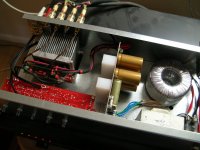
Just to share one of my favorite APEX collections LM3886 Chip Amplifer...
I can't stop my self to build again and again.....
I enjoy a lot with this very very nice amplifier of APEX
Regards,
Hi Wiljj78
Can you post this Layout with printable format for toner transfer method I want etch my PCB own. Thank you
Help on Apex Lm3886 Amply
Hi apexaudio
I build Your Apex lm3886 Amplifier. then i check all connection and any short connection but everything is ok Then I connect supply and all other connection . but when I start amplifier 1 to 2 second amplifier works fine and give output to speaker .but after few second amplifier get mute. it works again when i switch off and on power supply. My supply is +/- 30 VDC unregulated.and volume is not loud Enough. what is the problem in amplifier Please help me.
Thanks
Last edited:
Hi apexaudio
I build Your Apex lm3886 Amplifier. then i check all connection and any short connection but everything is ok Then I connect supply and all other connection . but when I start amplifier 1 to 2 second amplifier works fine and give output to speaker .but after few second amplifier get mute. it works again when i switch off and on power supply. My supply is +/- 30 VDC unregulated.and volume is not loud Enough. what is the problem in amplifier Please help me.
Thanks
did you attach a heatsink? look like its on thermal protect.check dc offset and chip's temperature
did you attach a heatsink? look like its on thermal protect.check dc offset and chip's temperature
Hello Drahcir
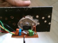
Please check the pic (not very clear )I have attached ,do you think my heat sink is not big enough ? . also you told to check dc offset but when i try to measure it
amp become mute and no reading on multimeter . i use toothpaste as thermal component in between mica and heat sink .
their is some resistance between IC metal tab and heatsink is it normal or
their is any problem. thanks
Attachments
and you expect us to respond with sensible solutions !i use toothpaste as thermal component in between mica and heat sink .
Heatsink is i think enough for testing if the amp work or not,how do you measure dc offset?it should be on the speaker out and gnd.kindly check the traces maybe something got shorted when you solder it and the polarity of the diodes
Sent from my Desire HD using Tapatalk 2
Sent from my Desire HD using Tapatalk 2
Heatsink is i think enough for testing if the amp work or not,how do you measure dc offset?it should be on the speaker out and gnd.kindly check the traces maybe something got shorted when you solder it and the polarity of the diodes
Sent from my Desire HD using Tapatalk 2
Hi Drahcir
I measure Dc offset as you mention. but before reeding showing on multimeter amplifier got mute. its only work 1 second every time I turn on power supply.
The heat sink would be ok for low power testing . The interface between your IC and your heatsink is a very important factor . You have two problems..
1. The toothpaste is acting as a thermal insulator.
2 The mounting tab of your IC will now more than likely have a bow in it. Especially if you got it nice and tight .
I suggest . Remove all tooth paste . get rid of the mica insulator as that looks like it has seen better days. get a piece of abrasive paper or a metal file and level face of heat sink.
Make sure the mounting tab of your IC is flat .
Put a washer on top of the insulating bush to help spread the tightening load .
Mount the IC directly to the heat sink. A little caution is needed as the heatsink will be at _ V rail potential . This will be ok for testing . Your heat sink is too small for any high power listening ....
Last edited:
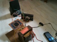
Do you have a temp gun or something that you can use to measure the temp of the ic? Also make sure that the heatsink doesnt touch anything,can you post a picture showing the components?might be a reversed diode or wrong value.the way i test a newly built amp is to measure first the output of the transformer then after rectifier then after power supply board,if all is ok then i connect if to the board,also do the light bulb test just search the forum for it.it looks like the internal protection of the ic is activating whenever you apply power to it.
Sent from my Desire HD using Tapatalk 2
Sent from my Desire HD using Tapatalk 2
Do you have a temp gun or something that you can use to measure the temp of the ic? Also make sure that the heatsink doesnt touch anything,can you post a picture showing the components?might be a reversed diode or wrong value.the way i test a newly built amp is to measure first the output of the transformer then after rectifier then after power supply board,if all is ok then i connect if to the board,also do the light bulb test just search the forum for it.it looks like the internal protection of the ic is activating whenever you apply power to it.
Sent from my Desire HD using Tapatalk 2
Hi Drahcir
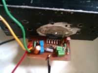
I made amplifier from layout of first post by apex audio. But in Layout and schematics their is some dereference. is that layout is correct or not because in schematics C4(10uf) + terminal is connected to R4 (15k) but in layout their is no connection between them please help me I am very confuse.
that layout is correct coz ive used that layout and schematic on my LM3886 build and its working perfectly, no hum/hizz ~10mv dc offset on both channel
upon inspection of your build, the 10uf capacitor is mounted in reverse polarity, negative side(striped) of the capacitor should be on top while the positive is at the bottom. kindly check
upon inspection of your build, the 10uf capacitor is mounted in reverse polarity, negative side(striped) of the capacitor should be on top while the positive is at the bottom. kindly check
- Home
- Amplifiers
- Chip Amps
- LM3886 Schematics + PCB