Terry, nice - creative approach with PCB upside down and the parts on the back side ")
247V is absolutely enough. Slightly rounded corners closer to 20KHz are also ok - having no global NFB loop, this design is neither super-wideband, nor super-fast. However, it performs very well within the audio range and I hope, you will like the sound.
247V is absolutely enough. Slightly rounded corners closer to 20KHz are also ok - having no global NFB loop, this design is neither super-wideband, nor super-fast. However, it performs very well within the audio range and I hope, you will like the sound.
I guess running the idle current at 2.2Amps makes it class A though the SS section looks like it has its' roots in a class A/B design with that complimentary pair. You are going to need a massive heat-sink.
Since you have it all simulated perhaps you should back down the idle current to something like 60ma and see if your distortion figures change. Looks like you could dub around with component values to try it.
I have a hybrid tube/ss state design that uses the very last section of a complimentary pair, class AB SS power amp. I used six transistors total (and two of them provide peak current limit), no op-amp to cancel idle current drift, about a handful of resistors, and an idle current trim pot - very simple. I do not use feedback. I do have an RTD mounted on the heat-sink to cancel drift and it is effective. This SS section has a gain of 0.9 being a voltage follower but who cares since the tubes driving them operate at such a high voltage signal level. Simulation of the SS section alone shows the THD to be less than 0.1% over the full bandwidth. This is a guitar amp so I don't really care to much about the THD in the tube section. In fact I've made effort to increase it in the tube section.
I get 70 watts with an idle current of 65ma, and Vrail of +/-42volts. No visible crossover distortion even at 100khz. The output transistors are a complimentary darlington pair coupled to the chassis thermally with a piece of angle aluminium - It gets warm but way below the threshold of pain.
I could send you the simulation/schem if you like. It's in TINA.
Hi Campsquare,
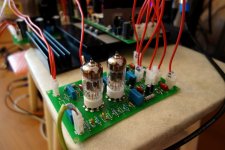
No, I also don't run it at 2.2Amps or even close to that. Class A output stage was considered as an idea at the very beginning of this project. At the later stage I came to using a HexFET class A/B OPS, running at 80mA per output pair (3 pairs of IRFP240/9240 in total).
The schematic "as built" can be seen >HERE<
I have set the overall voltage gain to 29db for compatibility with the other amplifiers.
With +/-70V rails and 1KW PSU I can have as much power as I like (up to around 250W @ 8 ohm) - way beyond my practical needs
Attached is the photo of the prototype exactly in this setup.
It would be interesting to see you design!
Cheers,
Valery
Attachments
Ok, I got a chance to hook up the boards to the Slewmaster OPS. It oscillates. It will sort of behave with no input and no load but as soon as I touch either PD+ or PD- with a probe, it will start to oscillate. I was actually able to get it to play a sine wave and square wave with no load on the output but at times that would cause oscillation too but with a load attached it goes almost instantly into oscillation. I'd like some ideas on where to try some fixes for this.
Thanks, Terry
Thanks, Terry
Mine oscillated as soon as I turned up the bias. I assumed it was because of slow predrivers and drivers. I haven't tried mine with the new drivers in my Slewmaster.Ok, I got a chance to hook up the boards to the Slewmaster OPS. It oscillates. It will sort of behave with no input and no load but as soon as I touch either PD+ or PD- with a probe, it will start to oscillate. I was actually able to get it to play a sine wave and square wave with no load on the output but at times that would cause oscillation too but with a load attached it goes almost instantly into oscillation. I'd like some ideas on where to try some fixes for this.
Thanks, Terry
My Slewmaster has KSA1831/KSC3503 predrivers, MJW3281/1302 drivers and MJL3281/1302 outputs. These outputs don't oscillate with any of the other IPS and I've built most of them. The only IPS that wouldn't work so far has been the Tubsumo. I had to use it with the Tubsumo OPS.
I had to step up to Sanken drivers to tame my Kypton-Cs. I think mine was 60hz oscillation but I had damaged my scope at that point. What's yours doing?My Slewmaster has KSA1831/KSC3503 predrivers, MJW3281/1302 drivers and MJL3281/1302 outputs. These outputs don't oscillate with any of the other IPS and I've built most of them. The only IPS that wouldn't work so far has been the Tubsumo. I had to use it with the Tubsumo OPS.
Oscillation looks really strange with this particular design. Normally, the reason for oscillation is the phase reverse in NFB loop at some high frequencies. No NFB loop - no oscillation.
The only signal, coming from the output, comes via DC servo. it is very slow by design, but... potentially there may be some artifacts, related to OpAmp stability. Can you try to run it with no servo installed (and no load for the time being). There may be some offset, but that's ok - let's see if it influences oscillation.
The only signal, coming from the output, comes via DC servo. it is very slow by design, but... potentially there may be some artifacts, related to OpAmp stability. Can you try to run it with no servo installed (and no load for the time being). There may be some offset, but that's ok - let's see if it influences oscillation.
I initially started up it up through a light bulb. Looked pretty good but as I said if I tried taking any voltage measurements it would start oscillating. The light bulb would do its job and lower the current. I then hooked it up without the light bulb and would hear sizzling as soon as it would oscillate. I shut it down in time to avoid any damage. I think it is close to working, just needs the proper compensation. Maybe it won't work with the Slewmaster but it would be nice if it would.
I still use it with 3-pair MosFET Slewmaster-based OPS with no sign of a problem. Interesting...
I haven't tried it with my MOSFET Slewmaster. I'll try it first with the servo removed and report back.
Thanks, Terry
OK, here's what I found. I pulled the servo. Offset is 24mv so not bad. I'm still using the light bulb and have the rails about +-42V. With no load attached it is still a little sensitive to a touch of the probe on the PD- but only very shortly and then settles. I have the bias set low for safety while I do this. I have 10mv across a pair of 0R22 emitters. With a load attached it actually seems more stable. It doesn't appear to be oscillating now but the weird thing is I am reading about 20V on PD+ and -20V on PD- where I would normally see 2V or less. The bias has not gone up though.
Awaiting instructions.
Awaiting instructions.
Hi Valery,
The deed is done. I dug a little deeper and found some 470p caps and soldered them to the lugs on the bottom of the boards. No more oscillation just beautiful music. Had it playing for about an hour now and everything is stable. Hopefully tomorrow I will set up another Slewmaster with a different IPS and A/B them. I want to give it time today to let the caps settle in. I don't have a protection circuit hooked up right now so I have to be careful how I start things up. It doesn't like having a load on it when starting. Speakers need to me disconnected during start up. It doesn't have a large voltage on the output like the Low TIM hybrid but it doesn't want to settle with a load attached. This was a fun one with the challenge of the board layout but it looks like it's going to be a keeper.
I'm running it at +-72V rails right now and it isn't breaking a sweat.
Thanks for another great design and thank you Jeff for sharing this with me.
Blessings, Terry
- Status
- This old topic is closed. If you want to reopen this topic, contact a moderator using the "Report Post" button.
- Home
- Amplifiers
- Solid State
- lGl-2, continuing "hybrid madness" - no GNFB class A