I'm thinking so. It worked fine before trying this one. With no signal I've got full high voltage rail on both sides of R5 in your schematic. 0 on pin 7 & 8 of V1. I think that's correct by your schematic? Will the difference in value of C5 cause any problems or just pass lower frequency?
I can't imagine what could cause such a high voltage at the grid. Normally, grid current is just some micro-amperes... So, being grounded via R1, it would have zero voltage, not blocking the signal due to its high impedance. The only thing, I can think of with regards to blocking the input signal is a shortened C2.
Couple of recommendations:
- always switch on heating first, before applying the high voltage to anode. So, first - 6.3VAC, then 250VDC;
- always use at least 1:10 divider at the oscilloscope probe when measuring such circuits, otherwise it's easy to kill the oscilloscope's input.
Looks like we are talking about the different schematics - I don't see neither R5, nor C5 on the one at post#35
All my components match the schematic in post 35. The pin markings are doubled up on that schematic though. My input is on pin 2. I guess I didn't miss an updated schematic then. I was comparing to the one you posted in 97.
I was using the 1:10 divider on the scope. I even checked for voltage on the inputs before connecting to it. I did plug in the charger on the laptop though. Possible ground loop? It may just be the signal generator part of it damaged. I haven't looked into it yet.
I was comparing to the one you posted in 97.I was using the 1:10 divider on the scope. I even checked for voltage on the inputs before connecting to it. I did plug in the charger on the laptop though. Possible ground loop? It may just be the signal generator part of it damaged. I haven't looked into it yet.
I'm thinking so. It worked fine before trying this one. With no signal I've got full high voltage rail on both sides of R5 in your schematic. 0 on pin 7 & 8 of V1. I think that's correct by your schematic? Will the difference in value of C5 cause any problems or just pass lower frequency?
Voltages at R5: +138V at the top end, +137V at the bottom one.
V1 - pin 7 is 0, pin 8 is 4.3V (4.3mA over R3=1K).
0 at pin 8 means there's no current through the tube.
C5 value only influences the low F pass, you're right.
All my components match the schematic in post 35. The pin markings are doubled up on that schematic though. My input is on pin 2. I guess I didn't miss an updated schematic then.
I was using the 1:10 divider on the scope. I even checked for voltage on the inputs before connecting to it. I did plug in the charger on the laptop though. Possible ground loop? It may just be the signal generator part of it damaged. I haven't looked into it yet.
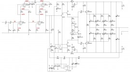
OK, so your triodes are just swapped - 678 at the top, 123 at the bottom. Then ok, 2 is the input. If the tube is good, it should work with no hassle. It's a straight forward common cathode cascade with the dynamic load. I mean... really, no chance to fail. That's why your measurements look very strange. Did you try some other tube, by the way?
OK, so your triodes are just swapped - 678 at the top, 123 at the bottom. Then ok, 2 is the input. If the tube is good, it should work with no hassle. It's a straight forward common cathode cascade with the dynamic load. I mean... really, no chance to fail. That's why your measurements look very strange. Did you try some other tube, by the way?
I've swapped between 4 different tubes and like an idiot I didn't mark the first one. I'm not getting high voltage on the input pin with any of them now. Bad day all around. I plugged in the wrong transformer and melted a cap multiplier in the output board I was using. I've got that repaired but I think I better wait until tomorrow to plug it in. I'm just burning parts today.
BTW, are you using your version of PCB (post #46)? If the picture shows the top silk and the tube is also placed on this side, then its pins numbering seems to go wrong direction. Your numbering goes clockwise, but the right one goes counter-clockwise (see my PCB layout in post #35). Could that be the cause? Or the tube is placed on the other side?
Voltages at R5: +138V at the top end, +137V at the bottom one.
V1 - pin 7 is 0, pin 8 is 4.3V (4.3mA over R3=1K).
0 at pin 8 means there's no current through the tube.
C5 value only influences the low F pass, you're right.
I went for it anyways.
I've got no voltage drop accross R6/5(this is way too confusing) and zero volts on both sides of R3. This is with an open input. Will a tube normally have an idle current through the cathode?BTW, are you using your version of PCB (post #46)? If the picture shows the top silk and the tube is also placed on this side, then its pins numbering seems to go wrong direction. Your numbering goes clockwise, but the right one goes counter-clockwise (see my PCB layout in post #35). Could that be the cause? Or the tube is placed on the other side?
That board had a bunch of errors. I've redrawn it since. I numbered them clockwise.
I went for it anyways.
Of course it has an idle current, it is set to 4.3mA here. Having R3=1K, you should have 4.3V across R3.
I'm just trying to figure out how this works. Is the top half a CCS like a BJT front end would have? Should R13 and R10(post 35) have current flow as well? They aren't passing current either. Is it possible I have a bad batch of tubes? These are all from one order.
Exactly, the top half is CCS, built the same way as it would be built with jfet (same topology). The secind cascade idle current is set to 5.3mA, so you should have 5.3V over R10.
One more thought (well, checking all the crazy ideas
) - are you sure you've got 6.3VAC at the heaters there? If it's not there - there will be no current through the triodes. No conduction. Do you see the orange light inside the tube (there are two heaters in each of them - one heater per triode)?These are Russian tubes. Maybe they keep the best and send the almost as good to Canada.
No, in most cases the best things are exported here
Tubes are fairly robust. But it cannot be the case that all your tubes are faulty. I've got one tube with some parameters out of normal range in my bunch, but it is one out of six, and it works anyway, just not as good...
So... no conduction is most likely the result of no heating.
Russia has better tubes.
OS
Well, this technology is still high quality here
No chance to produce a modern processor, but tubes - no problem
- Status
- This old topic is closed. If you want to reopen this topic, contact a moderator using the "Report Post" button.
- Home
- Amplifiers
- Solid State
- lGl-2, continuing "hybrid madness" - no GNFB class A