Whoops.. yes. 470k cathode bias resistor should be 470 ohm. Noticed the issues with the missing 100r resistor for the Tri/UL switch after I uploaded the image. I'm actually planning to have the cathode bypass resistor for the power tubes hooked to a DPDT switch so I can switch it to a higher value to allow for the use of kt88's.
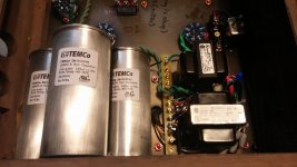
Regarding the capacitance of the PS; I already have the capacitors listed in the schematic.. would there be any detriment to having that much capacitance? I can fit them in the chassis (it's quite large).
1.5k instead of 560? Maybe.. 560 was a guess. I'm going to see what kind of power consumption I have once the circuit is assembled and powered up and adjust things accordingly.
Assuming these corrections are made, does this look like a reasonable schematic that can be powered up and operate properly? I'm sure I will need to tweak things once it's going.
I'll need to get it on a scope and take a look at the wave forms this thing puts out. Maybe add NFB. I'm not certain what kind of output power and distortion levels this amplifier will have, I'm not yet familiar enough with electrical formulae to estimate these values with just a schematic (If someone wants to break that down.. feel free, it'd be great).
I am concerned that I won't have enough gain to drive the KT150's with authority..
Thanks for the responses people, I really appreciate it.
Some Pics
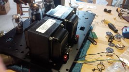
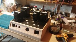
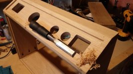
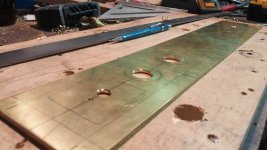
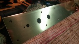
Rough assembly, making sure everything fits. Already found something that doesn't! Replacing all the stainless steel fasteners with brass.
More to follow.
Rough assembly, making sure everything fits. Already found something that doesn't! Replacing all the stainless steel fasteners with brass.
More to follow.
Attachments
It's Alive
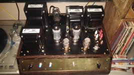
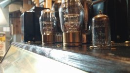
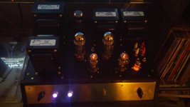
Well, it's alive. It amplifies.
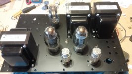
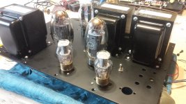
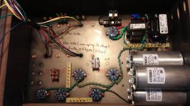
The circuit ended up being slightly different then the schematic I posted earlier, so I will post an updated version of the schematic when I've tweaked it to my satisfaction. The basic topology is still parallel 6SN7's driving KT150/KT120/KT88/6L6GC/EL34 power valves in U/L or Triode mode.
Power output is a little low, I think I need to refine some of the values to get more gain. Sound is CLEAN though, definitely loud enough for living room use.
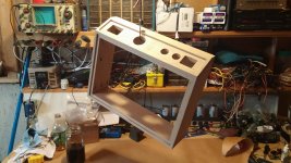
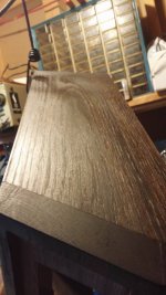
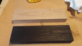
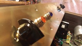
Chassis is White Oak finished with Iron Acetate (google it, pretty cool) and Tung Oil. Top plate it 1/4" 6061 Aluminum, and the Face Plate is 3/16" Cartridge Brass. Fender indicator lights and Glassware Audio power and input select switches.
I'm going to post a crap load of pictures below. I'll also post all of my power calculations for the different tubes running in different modes. There are two switched on the top plate; One for U/L and Triode, the other switches out the cathode bypass capacitor on the power tubes (560 and 360 Ohm - Low/High power). Once the values and schematic are posted, I would appreciate opinions on how to improve the performance of this amplifier.
Thanks for everyone's help so far. This project is operational, but now the fun part begins... Listening and tweaking.
Oh, and it's heavy. Really. Heavy.
Well, it's alive. It amplifies.
The circuit ended up being slightly different then the schematic I posted earlier, so I will post an updated version of the schematic when I've tweaked it to my satisfaction. The basic topology is still parallel 6SN7's driving KT150/KT120/KT88/6L6GC/EL34 power valves in U/L or Triode mode.
Power output is a little low, I think I need to refine some of the values to get more gain. Sound is CLEAN though, definitely loud enough for living room use.
Chassis is White Oak finished with Iron Acetate (google it, pretty cool) and Tung Oil. Top plate it 1/4" 6061 Aluminum, and the Face Plate is 3/16" Cartridge Brass. Fender indicator lights and Glassware Audio power and input select switches.
I'm going to post a crap load of pictures below. I'll also post all of my power calculations for the different tubes running in different modes. There are two switched on the top plate; One for U/L and Triode, the other switches out the cathode bypass capacitor on the power tubes (560 and 360 Ohm - Low/High power). Once the values and schematic are posted, I would appreciate opinions on how to improve the performance of this amplifier.
Thanks for everyone's help so far. This project is operational, but now the fun part begins... Listening and tweaking.
Oh, and it's heavy. Really. Heavy.
Attachments
-
 16106979_1401362629894957_2090646267_o.jpg192.4 KB · Views: 280
 -
 16010615_1401360649895155_1694874718_o.jpg187.3 KB · Views: 273
 -
 16010562_1401362416561645_668746599_o.jpg266.6 KB · Views: 269
 -
 15966488_1401362566561630_1070140885_o.jpg195.5 KB · Views: 227
 -
 16107975_1401361879895032_1618183845_o.jpg196.6 KB · Views: 240
 -
 16106087_1401362189895001_7803007_o.jpg188.4 KB · Views: 289
 -
 16009816_1401360479895172_2076957568_o.jpg307.9 KB · Views: 320
 -
 16010261_1401361409895079_1564046716_o.jpg245.6 KB · Views: 334
 -
 16122277_1401361423228411_412270893_o.jpg184.5 KB · Views: 697
More Pics
More pics..
More pics..
Attachments
-
 16009753_1401360256561861_2059758144_o.jpg284.9 KB · Views: 730
 -
 16108031_1401361146561772_481553818_o.jpg175 KB · Views: 697
 -
 16106154_1401360389895181_623710902_o.jpg175 KB · Views: 246
 -
 16121997_1401362186561668_1130062939_o.jpg197.1 KB · Views: 649
 -
 16106580_1401361119895108_2002823906_o.jpg184.1 KB · Views: 647
 -
 16106173_1401360956561791_295283009_o.jpg135.4 KB · Views: 660
 -
 16107600_1401361819895038_186442666_o.jpg204 KB · Views: 272
 -
 16107716_1401359926561894_981961949_o.jpg134.8 KB · Views: 294

Amp Continues..
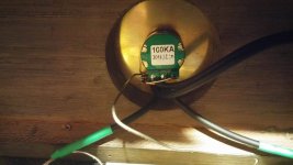
I cut the top plate to accommodate a 6N1P tube that I didn't end up using because I changed the design, it's just there to fill a hole. Need to find something clever to do with one 6N1P.
Schematic will be forthcoming, I need to make a few alterations. The amplifier operates, but I'll have to adjust the operating points.
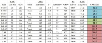
Here are the voltages and such that I'm getting from this amplifier at the moment with KT150's, 6L6GC's, and EL34's
The EL34's are being operated outside their ratings, especially in the "High Power" mode, they red plate a little bit, but WOW do they sound good! I've got all kinds of EL34's and 6L6's from back when I was a gigging musician, so I'm not too worried about toasting a few during testing.
The "High Power" mode is for the KT150's, I don't think I'll end up subjecting the poor EL34's and 6L6's to this mode, despite the fantastic sound they put out.
The "Low/High Power" switch is for a 560 and 350ohm cathode resistor on the power tubes.
See image.
I cut the top plate to accommodate a 6N1P tube that I didn't end up using because I changed the design, it's just there to fill a hole. Need to find something clever to do with one 6N1P.
Schematic will be forthcoming, I need to make a few alterations. The amplifier operates, but I'll have to adjust the operating points.
Here are the voltages and such that I'm getting from this amplifier at the moment with KT150's, 6L6GC's, and EL34's
The EL34's are being operated outside their ratings, especially in the "High Power" mode, they red plate a little bit, but WOW do they sound good! I've got all kinds of EL34's and 6L6's from back when I was a gigging musician, so I'm not too worried about toasting a few during testing.
The "High Power" mode is for the KT150's, I don't think I'll end up subjecting the poor EL34's and 6L6's to this mode, despite the fantastic sound they put out.
The "Low/High Power" switch is for a 560 and 350ohm cathode resistor on the power tubes.
See image.
Attachments
Good job! There is a lot of labor in this project! You have good skills!
I bet you've acquired a lot of experience from building this amplifier and there are vasts amounts of it remaining to be learned, it depends where would you like to stop.")
Congratulations! I'll be keeping an eye on.
I bet you've acquired a lot of experience from building this amplifier and there are vasts amounts of it remaining to be learned, it depends where would you like to stop.
Congratulations! I'll be keeping an eye on.
- Status
- This old topic is closed. If you want to reopen this topic, contact a moderator using the "Report Post" button.
- Home
- Amplifiers
- Tubes / Valves
- KT150 SE based on Mikael's KT88 Schematic