Oooh.. thanks.
Where would the 5v CT go? Could you explain that a little more?
The CT of the 5v winding is the B+ source. This is a nice way to begin your power supply filtering section. If your 5v supply for the tube rectifiers did not have a CT, then you would take the B+ off pin 8. A 5vct, again, does away with that requirement. Some builders, myself included, like that. cheers, Dak
Never mind, CT grounded would short the B+ to ground. Don't think I want to use it as my B+ source, I might want to run an indirectly heated rectifier (5AR4) so I'll just leave the 5v CT open and taped off.
If you run a 5ar4 rectifier you will need a 5v filament source. you will need that tap.
Please do!I shall continue to post progress updates anyway.
")
The 1mV you specified earlier is good for a wide range of amplifiers as a broad guideline, and is easy to achieve with a little care. Acceptable noise performance at the output is going to depend on the sensitivity of your speakers.Okay.. how about CLCLC (Output B+) RC (Input B+).
Is there still too much resistance? Are two LC stages too much?
You can consider the supply rejection ratio of a stage along with the gain structure to ensure that each stage is fed with an appropriately quiet rail so that its contribution to output noise is not dominant.
Low impedance in the overall supply shouldn't sway you from good design. Eg there should be a certain amount of damping resistance before the first cap. Using PSUDII is good here. I think this contributes a part of what could be a subjective argument against solid state rectification (ie poor design).
Instead, you could use a large capacitor at the end of your ripple filter. This low impedance will feed the amp and form a barrier to the earlier filter stages from the amp stages. You'd have to make it work with the last choke, of course.
Last edited:
Just looked at your schematics.
The amp shows 400V on the 6sn7's but the power supply shows 250V.
I did a KT150 SE amp with a 6.5K OPT (I had them on hand) and still needed some feedback to get the output impedance down and hence the damping to a usable level.
Mine used a 6bn4 driver into the KT150 and I used a 220K resistor between the plates for Schade type FB. That worked very well with LED bias.
The 400V plate supply is good if you want to be able to use KT88s or 6550s in the future but if it's just KT150s you can raise the B+ for more power output.
Hi from Greece! If you want use these tubes,must build the circuit,from china,who post the member rotaspec from NZ ,in post 4,in your thread! These tubes is powerfull,and needs high voltage,and more drive! 500v is not problem for these tubes! I built before 1 month,a RH amplifier.universal circuit version 2 I use 6550 tubes at first, use James 6123hs OTs ,at 2.5k tap,i test kt88,and kt120 tubes. The KT120 tubes sounds very good,but i like more the kt88 sound,and 6550 ,not bad!I use 420v for power tubes,and about 186v in drive tube,please take a look in RH6550 SE amplifier thread for more details and schematics! The bias of kt120 its almost the same,like kt88,no more power at all! The only advantage is relaxed kt120,who lasts forever! If you wanna the power of KT150 built the chinese schematic!
The other way to think about it is; Why make a SE amp if you want to use 3 stages?
The whole KT88 through KT150 and 6550 family are not difficult to drive and don't really require the extra stages unless you just want to use more tubes. There's little Miller effect and the higher gain from beam power tubes make the multi stage driver redundant.
Use a higher mu driver and get a simpler two stage amp that doesn't invert polarity. You have a simpler power supply and you don't put three stages inside a global feedback loop.
Unless, of course, you just need bigger equipment
Thread is alive again!
There have been changes to the circuit I intend on using. It has been simplified, and I will most likely be attempting to drive the KT150's with the 6SN7's running as parallel triodes. The 6N1P may not be used.. although I already have it mounted on the chassis. In which case I will need to find something interesting to do with a single 6N1P.
Based on my testing, I believe the B+ will be much higher that 400v. More like 450v-500v, I'll have to see how everything settles once the circuit is complete, and energized. I would still like to run KT88's/6550's but I may need to have some sort of switchable B+/cathode bypass resistor in order to bring the voltage and current down to a level where they will operate without going into atom splitting mode. I'll try and post updated schematics this weekend. I admittedly don't know a whole lot about the ins and outs of constructing a valve amplifier, which is why I really appreciate and assistance you fine people can provide.
Stay tuned.
The 6E5P is often used to drive 6C33C tubes in a two stage SE amp. I've used it myself loaded with a Gary Pimm CCS at 15 ma. You can get the general idea by looking at the driver section of my version of such an amp. Ignore the rest of the amp.
Audio ratbag: Cat Vomit Special - a 6E5P / 6C33C parafeed amp
You could also use CCS of cascoded DN2540s. An example follows:
http://www.diyaudio.com/forums/attachments/tubes-valves/336507d1363472446-help-dn2540-ccs-design-schematic-large.png
More about the 6E5P at 6e5p triode-strapped | Bartola Valves
It's a fine sounding tube.
ray
Still alive.
Well I'm back. Sometimes life gets in the way of my projects.
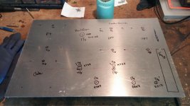
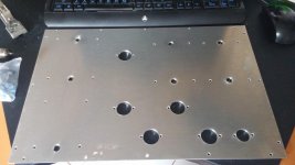
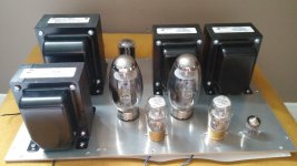
Top Plate is out being powder coated, and the chassis design has been submitted to a cabinet maker. Looks like this thing is actually going to happen!
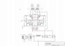
I've put a circuit together, but I'm not sure if the values I've used for the resistors and caps are correct (I think the power supply is good). Parallel 6SN7's going to KT150's in SE Class A.
I'm really hoping for some opinions before I start soldering. I may have missed something, and the more eyes the better.
Well I'm back. Sometimes life gets in the way of my projects.
Top Plate is out being powder coated, and the chassis design has been submitted to a cabinet maker. Looks like this thing is actually going to happen!
I've put a circuit together, but I'm not sure if the values I've used for the resistors and caps are correct (I think the power supply is good). Parallel 6SN7's going to KT150's in SE Class A.
I'm really hoping for some opinions before I start soldering. I may have missed something, and the more eyes the better.
Attachments
I assume the 470K cathode resistor on the KT88's (KT120's) should read 470 ohm's?
yes I saw that too.
- Status
- This old topic is closed. If you want to reopen this topic, contact a moderator using the "Report Post" button.
- Home
- Amplifiers
- Tubes / Valves
- KT150 SE based on Mikael's KT88 Schematic