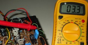
Not now because i am busy..but later i will solder multimeter proble points into
those transistor colectors...and the voltimeter will be reading the voltage...so... this will remove doubts if i have measure correctly or not.
I could not find more than 1.5 volts into my simulator... reason why i do not turst on it... this happens... and not a rarity to produce fake readings.
Analisis are always very good...what a hell!... i have tested bad amplifiers and simulations were good?
Carlos
Re: Not now because i am busy..but later i will solder multimeter proble points into
Hi Carlos,
Have you fixed your circuit in your simulator? I could see at least 4 errors, a couple of circuit errors and a couple of values out by an order of magnitude (ref: circuit in post #42).
regards
destroyer X said:I could not find more than 1.5 volts into my simulator... reason why i do not turst on it... this happens... and not a rarity to produce fake readings.
Hi Carlos,
Have you fixed your circuit in your simulator? I could see at least 4 errors, a couple of circuit errors and a couple of values out by an order of magnitude (ref: circuit in post #42).
regards
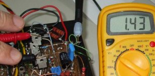
Yes Greg... i have fixed errors into the simulator and i have re-adjusted ...
And i am sorry... really the voltage is around 1.5 volts.... was misadjusted last time.
Now i have the amplifier better in adjustment...continue to sound very good.
Here you have the off set.
Carlos
And i am sorry... really the voltage is around 1.5 volts.... was misadjusted last time.
Now i have the amplifier better in adjustment...continue to sound very good.
Here you have the off set.
Carlos
Attachments
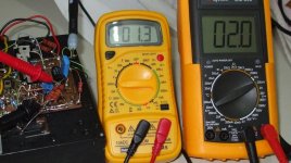
Here you have the current over the output emitter resistance,
So, it is the output stage current.... transistor just conducting...class A operation with very small iddle consumption.
Also you have the off set.... depending the adjustment you can have something from -5 milivolts to +5 milivolts.
My power on sub sonic non audible "thump" disappeared with better off set adjustment as Steve Dunlap said.
I see that we have different results tweaking stand by current.
regards,
Carlos
Attachments
I have to say that i think sound goes better when i increase output current
something from 70 to 120 miliamperes... also i love when off set goes misadjusted to 50 milivolts.... of course not the fact the offset is out from standard, but the sonic result.. speaker moves forward 2 milimeters.
But sounds fine with smaller current too.
I have to read once again Steve's instructions about adjustment.
regards,
Carlos
PCB for Krill amp ....
Hi ,
I'am happy to make a PCB for Krill amp , nice schematic , and sound good if uncle Carlos speak so beautiful about this amplifier .This is my contribution http://i35.tinypic.com/34ybhok.jpg Regards alex mm
Please any comments are constructive !
Hi ,
I'am happy to make a PCB for Krill amp , nice schematic , and sound good if uncle Carlos speak so beautiful about this amplifier .This is my contribution
http://i35.tinypic.com/34ybhok.jpg Regards alex mm Please any comments are constructive !
It's fantastic to hear such glowing reports on the sonics of this amp - thank you again Steven for your unselfishness in posting your schematic here and answering a lot of questions.
It's unusual to see a new take on the working of an output stage and even more unusual for it to be posted here. I for one feel that you should benefit from this and suggest that any pcb for group buys should reward you in some way.
Did you say c2cThomas was putting something together along these lines, when he has some time free from looking after his wife?
So, Alex & Troystg, thanks for offering the pcb but maybe we should all wait for what Steve says.
One suggestion - I would be interested in an output stage only pcb as I would run this from a tube front end
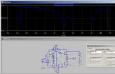
Transconductance of the whole output circuit plotted as a function of output current. It gets better the more *mismatched* parts you use because the deadband will be moved outside the working range of the amplifier. So with real parts it will be better but why do an output configuration that depends on mismatching to work correctly?
Attachments
jkeny said:
Did you say c2cThomas was putting something together along these lines, when he has some time free from looking after his wife?
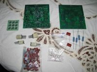
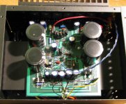
I drove over for a visit with Steve D. today and we put together a little Christmas package for Carlos -

The circuit boards in the photo are for Steve's old monoblock amps - but they are much less complex than the standard boards he used when he was manufacturing units for resale. Those boards - and the amplifiers - were very complex and not for the average DIY type of project. That's why Steve redrew the schematic for the DIY crowd. Some redraws have been done after the original to correct some things and juma did a very nice redraw that makes the circuit very clear.
I know that Steve is willing to help out all that he can with a PWB layout - and he has a number of parts (box's of nice xformers) that could be used in a GB if there is enough interest to get one going.
I'm willing to help Steve - and our little group here
 all that I can between caring for my wife (doing very well) and my wonder dog Manfred (still recovering from back surgery). It's about 45 miles one-way to Steve's place - so I would just as soon not make that drive on a daily basis - but once or twice a week could work.
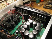
I took some photo's of Steve and his amp and Carlos has them in hand to be seen soon on a web page near you!
ps Steve and his Wife Mary are celebrating wedding anniversary this evening - so I don't expect to see him around until tomorrow.
Attachments
jkeny said:Happy Anniversary Steve & Mary
Great to hear your wife is doing well, Thomas
Ta Mate (and a big arf-arf from Manfred).

BTW - I'm a Shannon - 3 generations replaced!
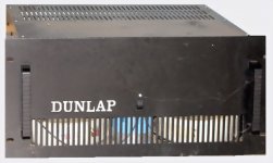
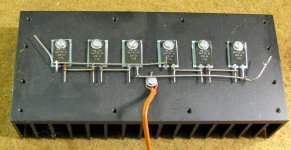
Photo of Steve's commercial unit - this one is like 7 or 8 years old. It might give you an idea why Steve doesn't think it would be a good candidate for a DIY project. 
It weighs 90 lbs (45 kilo). This unit was dropped in shipping and it busted a couple of the circuit cards loose - but the case didn't get hurt a bit. Ya gotta respect a case like this one - if you don't it will hurt you!
It weighs 90 lbs (45 kilo). This unit was dropped in shipping and it busted a couple of the circuit cards loose - but the case didn't get hurt a bit. Ya gotta respect a case like this one - if you don't it will hurt you!
Attachments
Thank you Steve Dunlap and Thomas Jennings...
Next years first days i will have those parts and boards in my hands.
Duda will take care of them.
Thanks by the pictures Thomas...i am already downloading them.
Here you have Mr. Dunlap picture... a nice and handsome redish guy (redneck?)...ahahahahaha.
regards,
Carlos
Next years first days i will have those parts and boards in my hands.
Duda will take care of them.
Thanks by the pictures Thomas...i am already downloading them.
Here you have Mr. Dunlap picture... a nice and handsome redish guy (redneck?)...ahahahahaha.
regards,
Carlos
Attachments
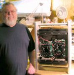
You see... Dunlap is intelligent....he do not believe in specifications entirelly
He use to check heatsinks using real power on them... this way he will see the real thing forcing current from colector to emitter...and distributed into all heatsink block.
The man use to engage the brain.
I love those folks.... i call them a "non bureacratic dyers"... he use to solder...nows theories, uses computers, use calculations, but check them all into real world.
A complete guy in my point of view.... the result is clear....listen his amplifier and you will understand what i mean!
He is offering a DIY option, a working version of his commercial amplifier... a great chance of all of us.
Carlos
Attachments
- Status
- This old topic is closed. If you want to reopen this topic, contact a moderator using the "Report Post" button.
- Home
- Amplifiers
- Solid State
- Krill - The little amp that might...