Ok,
I didn t get the idea I guess. So I will try with 50mA bias, to me it s quite optimal for bjts. For sure the crossover distortion must be lesser than with the super low bias I had. I swear someone said this amplifier was cold running in the old thread... Weird...
Regards
I didn t get the idea I guess. So I will try with 50mA bias, to me it s quite optimal for bjts. For sure the crossover distortion must be lesser than with the super low bias I had. I swear someone said this amplifier was cold running in the old thread... Weird...
Regards
h_a said:Hi Steve and Darian,
the 200mA bias is more or less a random bias number - it's not optimized in any way. As I distrust simulators I didn't bother to sim multple bias points to find the minimum.
What I see in simulation and what I would be interested in is that the sim predicts that the current in the "passive" bjt becomes smaller with increased output current - to a point where the current goes into microamp region. That certainly cannot be correct as that's already more or less turn-off.
Steve, maybe could you comment on that? How does the bias current in the "shut-off" transistor behave with increasing output current in the real circuit?
Does it always stay the same?
Have fun and thanks a lot for your support! Hannes
EDIT:
Hey that's peanutsI'm more used to ClassA amps

Hi h_a:
I will try to take your questions and observations in order. The bias transistors do indeed approach cutoff. They can not however ever actually cut off. When one conducts less current in the emitter then the base current is reduce in BOTH of the bias transistors. This causes both of them to approach cutoff. As I said however they cannot reach cutoff. If that happened there would be no escape route for the current source and BOTH output transistors would turn fully on and that would not be a good thing. If the bias transistors get to close to turnoff then the voltage on the emitter goes higher forcing them to stay on.
The base current in the bias pair does fluctuate with output current. That is why the outputs stay on. But keep in mind, even though the base current varies, it is always equal for both transistors because their bases are in series.
I hope that helps some.
Steve
This is very clever, very interesting and works great
I am listening!
Sound seems is coming from heaven... clear advantage compared to more standard designs....very clear the advantage...and sounds great with ANY kind of speaker.
I suggest you folks to build.
And prepare yourself for extreme great emotions... a sonic orgasm into your life.
If you have problems in your heart..some disease... please do not try...emotions will be great because sound comes alive in a beautifull way.
I am sending 5 hertz, full power and no noise...no sound and no noises..amplifier is almost perfect... not perfect because have power-on huge thump.
ahahahah...not a real problem, of course.
regards,
Carlos
It is not a real problem Steve...and really not a power on thump
The speaker is moving forward a little... a noiseless movement..all i could listen is the switch flipping.... it is not a thump, nor a tone, nor a supply hum...half cicle movement during 3/4 of a second... just condensers charging some place.... this movement can be something we can call infrasonic...subsonic frequency...and half cicle only...from the rest position to the positive side.... well.... i have not matched parts.
Up i am using TIP42 because i have found a BD140 (PNP) having some leakage... so...upper position i have a TIP42 and down i have a BD139
Those condensers produces a delay while charging.... i think reducing them will finish...but really this is not bothering me.
You know... all i could find to say something negative is this...ahahahahah.... i was trying to be funny.... you know... your amplifier has protection against criticism..hard to find defects to say something negative.
Those amplifiers are hard to say something because we look alike an idiot saying good, great, lovely, beautifull, excelent and nothing bad to say... seems we are idiot and we cannot perceive nothing wrong when this always happens..nothing is perfect in this world.
The off set is zero!....... bias is 50 miliamps.
Delicious..... just delicious sound!
regards,
Carlos
Hi Steve,
thank you for the kind words. I admire your unselfish sharing of a nice circuit with DIY-ers.
Many times before we witnessed here promotions of different amp circuits which were done with sole intent of creating a hype to boost kits and amps sales, but you renounced that from the very start which puts you together with rare, talented, people who were willing to generously share their achievement with DIY community and help others enjoy the music and DIY spirit in more profound way. You have my praises for that.
Thanks again and God bless you
This one seems to be the latest.... was the latest produced and published
And it is working in my home...so..it is correct, reliable, you can trust the schematic is fine.
This nigth was operating over a dummy load, all nigth long, 30 watts of power having sinusoidal 1 Kilohertz tone... no thermal drift, no problems.
The dummy load used has inductance because coiled, has resistance and capacitance...so... it is something that use to unstabilize bad amplifiers...there's absolutelly no problem about stability into this amplifier...no RF capture..you can put your finger into the input and no broadcast is tuned!...it is a rock stable unit.
A real Masterpiece of excelency as an audio amplifier!
regards,
Carlos
Attachments

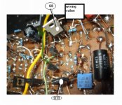
Mine has 2.34 Volts Mihai
I hope you are healing because that bone broken.
It operates class AB.... 0.55V each transistor.... well... at least mine is working this way.
I am not sure mine is perfect... i have a big mess of parts, wrong resistances, unmatched transistors and all kinds of mess.
Even this way it is sounding great.
Your amplifier sounds special too.
regards,
Carlos
Attachments
It seems to me the circuit avoids the output to go switching
Maybe i have misunderstood something.... but.... i have injected 5 hertz...and off course we are not able to listen this frequency... and the speaker used is a silent one...moves without fluft, flaft, plaft, pléft or any kind of "plastic" noise... so.... if we listen something when you drive the amplifier hard...of course bellow clipping but near the clipping, then you cannot listen output transistors switching noises... and really i could not listen any switching noise....because of that i think, if it is switching, it is doing in a better way.. at least without spikes, or any kind of transient spurious noises.
Speaker silent.... tone we cannot listen and noises not listened too .... and noises we can listen modulating the silent (for us humans) 5 hertz sinusoidal tone.
regards,
Carlos
Re: Mine has 2.34 Volts Mihai
Hi Carlos,
The bones are healing well. Thank you for asking.
In simulator I never get more than 500 - 600mV Vce over Q8 and Q11 transistors, which is strange. It is impossible to simulate this output stage.
Anyway, I trust Steve and you also and I will build for evaluation a version with three pairs of ThermalTrack power devices.
Cheers,
Mihai
destroyer X said:
I hope you are healing because that bone broken.
It operates class AB.... 0.55V each transistor.... well... at least mine is working this way.
I am not sure mine is perfect... i have a big mess of parts, wrong resistances, unmatched transistors and all kinds of mess.
Even this way it is sounding great.
Your amplifier sounds special too.
regards,
Carlos
Hi Carlos,
The bones are healing well. Thank you for asking.
In simulator I never get more than 500 - 600mV Vce over Q8 and Q11 transistors, which is strange. It is impossible to simulate this output stage.
Anyway, I trust Steve and you also and I will build for evaluation a version with three pairs of ThermalTrack power devices.
Cheers,
Mihai
Re: It seems to me the circuit avoids the output to go switching
Yes I beleve in that but it is interesting why th simulation fails..
destroyer X said:
Maybe i have misunderstood something.... but.... i have injected 5 hertz...and off course we are not able to listen this frequency... and the speaker used is a silent one...moves without fluft, flaft, plaft, pléft or any kind of "plastic" noise... so.... if we listen something when you drive the amplifier hard...of course bellow clipping but near the clipping, then you cannot listen output transistors switching noises... and really i could not listen any switching noise....because of that i think, if it is switching, it is doing in a better way.. at least without spikes, or any kind of transient spurious noises.
Speaker silent.... tone we cannot listen and noises not listened too .... and noises we can listen modulating the silent (for us humans) 5 hertz sinusoidal tone.
regards,
Carlos
Yes I beleve in that but it is interesting why th simulation fails..
Hello,
To Bogdan,
Now I don't feel alone anymore! As you can see in this thread, I had the same problem as you, it is switching. I still not completely get how it is supposed not to switch off but that is another story...
To Dx
If there is a switching distortion in Steve circuit, it would be very low anyway (let's say at the very very max -70dB, more like -80dB) and typically high frequency. I can see the capacitor C11 (between the bases of the drivers Q13 and Q14) would make a good job of accelerating the reverse biasing and switching off of the drivers (if they switch off...). It would be even more effective if placed between the bases of the output transistors, typically more prone to charge build-up (if these switch off...).
And even more important, switching distortion tends to vanish at low frequency because it's a speed charge and discharge problem (but not crossover distortion, that's how you easily sort them)!!! That's why you would typically use a 10kHz wave to track this phenomenon!
Finally, like crossover distortion, it doesn't vary much in absolute value with raising power output. That's why it's mainly a problem at low power, causing the usual "V" shaped distortion curve of the class B amplifiers.
So, I am not sure you would be able to hear it in your 5Hz set-up anyway!
That said, I don't put in doubt Steve amplifier has the capability not to switch-off! But a real measurement of the current through the output device would be more accurate to observe it.
Regards
Hi Bogdan, could you please be more elaborate? Maybe we both see the same, but interpret differently.
At at least small currents (below 1Apk) I do see a sliding bias effect, as also the plot of one of my previous posts shows.
For large output currents sim predicts only microamperes of bias current for the "passive" transistor - but this also depends on the chosen DC-bias current.
@roender: would be great if you could build a prototype and post your measurements here! There's certainly a lot interest
Have fun, Hannes
EDIT: @Darian: you got mail
h_a said:Hi Bogdan, could you please be more elaborate? Maybe we both see the same, but interpret differently.
At at least small currents (below 1Apk) I do see a sliding bias effect, as also the plot of one of my previous posts shows.
For large output currents sim predicts only microamperes of bias current for the "passive" transistor - but this also depends on the chosen DC-bias current.
@roender: would be great if you could build a prototype and post your measurements here! There's certainly a lot interest
Have fun, Hannes
EDIT: @Darian: you got mail
h_a could you post your simulation file?
- Status
- This old topic is closed. If you want to reopen this topic, contact a moderator using the "Report Post" button.
- Home
- Amplifiers
- Solid State
- Krill - The little amp that might...