Steve,
I know it is not really cascoding, that's why I used "". But these 2 transistors ultimately set up a defined difference of potential between 2 points of the circuit so it's not that far, just a little more dynamic than the real one. I just couldn't remember the numbers so I couldn't name them. I guess it's Q8 and Q11 according to the thread. They also set the current flowing through the output devices so why not call them "polarizing?".
I believe you in the good results you obtained and you are far more experienced than me with amplifiers. I just would like to understand better and how could it be so different in Microcap and in real life? Do you think they are not operating in saturated mode? With a Vce less than 1 V there is some chances (even more with only 2 diodes, 3 diodes make more sense to me). I understand the trick is variation of Ib and the change in apparent resistance it produces (saturated mode operation, again). What I don't understand is how this slight variation can be controlled without an extremely tight matching of transistors and the precise set us of the saturated mode equilibrium by choosing the diodes with extensive care (if it's a too low Vce, the Ib has not much influence anymore). It looks very hard to trim in real life.
Nevertheless, it's a very interesting circuit since we can talk about it for many pages!
Regards
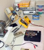
Dnnlap Amplifier is assembled... i will have to travell downtown
.... and today i will submit it to a triple check, a cleaning and they will switch power on to adjust and play nice music.
Be happy folks...i am working to be happy.
It is not pretty...this is macho amplifier....made by a man.... a "mucho macho" amplifier.... a real male one.
Soon i will be back
Enjoy your life folks....it finishes very fast!
Carlos
Attachments
Nice job, redrawing the schematic.
It looks more like a variation of the Blomley design - I don't like the fact that the output transistors have no RC network between their bases (see D.Self EFII) to speed up turn-off.
Great design though, Mr.Dunlap; I will definitely build this with BD159/BD140 and TIP142/TIP147.
It looks more like a variation of the Blomley design - I don't like the fact that the output transistors have no RC network between their bases (see D.Self EFII) to speed up turn-off.
Great design though, Mr.Dunlap; I will definitely build this with BD159/BD140 and TIP142/TIP147.
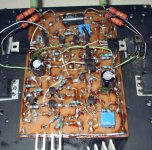
I have to check.... but seems finished...maybe one or two resistances wrong place
also i have to pre adjust trimpots and produce some measurements.... then cleaning and JOY!
Maybe will not clean...macho amplifier... with sweet and dirty things...some drops of wiskie and beer around... some hairs falling down over the board... a potato chips around... a male amplifier understand?
Carlos
Attachments

Re: I have to check.... but seems finished...maybe one or two resistances wrong place
Ahhh - I can smell what you are cooking all the way from USA. Don't let the magic smoke escape from the transistors!!
1. I will visit with Steve on Sunday - get some parts and take some photo's of his amp and workshop.
2. Manfred the wonder dog's back surgery went very well and he is able to stand up! Not walking yet - but getting better fast. I hope to bring him home Monday or Tuesday.
Carlos - you are crazy good!!! Wonderful!!!
destroyer X said:
also i have to pre adjust trimpots and produce some measurements.... then cleaning and JOY!
Maybe will not clean...macho amplifier... with sweet and dirty things...some drops of wiskie and beer around... some hairs falling down over the board... a potato chips around... a male amplifier understand?
Carlos
Ahhh - I can smell what you are cooking all the way from USA. Don't let the magic smoke escape from the transistors!!
1. I will visit with Steve on Sunday - get some parts and take some photo's of his amp and workshop.
2. Manfred the wonder dog's back surgery went very well and he is able to stand up! Not walking yet - but getting better fast. I hope to bring him home Monday or Tuesday.
Carlos - you are crazy good!!! Wonderful!!!
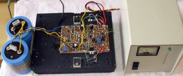
This beautifull amplifier is playing loud and clear
with a exceptional, outstanding sonics.
All controls working fine....but i have some damaged parts (all old junk parts i am using) or mismatch is bothering me a little.... having off set zero sound is not so beautifull compared when i am using it with some off set.
I am trying 500 miliamperes...well...for sure i have something wrong there, resistances wrong value or something...and even this way it is reproducing a hell good sound!
Cristal clear trebles, deep and deeper and strong bass... wonderfull amplifier the way it is today.... imagine tomorrow folks!
regards,
Carlos
....................................................................................................
Fine Thomas
Please, capture some 1N4148 and ask for matched transistors for critical position...i will try to find better parts to reassemble the output.
Carlos
Attachments
Hello,
Juma, I see you put the circuit in a simulator. How are the results distortion-wize? Is there a big crossover distortion? I put the output stage in Microcap in a previous thread (looking like a diamond buffer since that's what it is) and got these voltages :
http://www.diyaudio.com/forums/attachment.php?s=&postid=1664004&stamp=1227235157
The original circuit had only 2 diodes, anyway? Maybe the software you use can have a better results in simulation? Microcap can't seem to reproduce it the way Steve describes it working...
Regards
Hello Carlos!
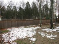
Two days ago we had this weather "thingy" called "snow". Perhaps you have read about it.
It's is cold here - about 1c - so think coooooooool thoughts!!!
ps - I took this photo just a few minutes ago. Yesterday the entire yard was covered - plus I had to remove some snow from the driveway so I would not slip and fall on the way to the mail box.
Attachments
I don't like the fact that the output transistors have no RC network between their bases (see D.Self EFII) to speed up turn-off.
That's a sliding bias scheme, no turn-off here (see pic).
Glad to see that a discussion started!
@Darian: sorry, I have no simfile that would contain only the outputstage!
The attachment shows a variant of Steve's outputstage with 200mA bias current; you see that the transistor stays on through the whole cycle (26mA minimum).
Distortionwise I find about 0.011% THD at shown output current into 8R (depends of course also to the rest of the amp).
To which extent this agrees with Steve's experience I don't know as my variant is not fully trimmed yet (no time so far).
Have fun, Hannes
EDIT: the distortion is dominantly 3rd harmonic (about 0.01%).
Attachments
darian said:Hello,
Juma, I see you put the circuit in a simulator. How are the results distortion-wize?....
I posted it here:
http://www.diyaudio.com/forums/attachment.php?s=&postid=1683644&stamp=1229130212
Fundamental (10KHz) is 24 V and the harrmonics' amplitudes are shown in the picture. Just calculate relations between any of them and fundamental. The result may not be very realistic, and my question to Steve was more about comparing harmonic content distribution to real life circuit ...
Carl_Huff said:Steve,
Interesting design. I have just found this thread and am studying your design. Have you ever considered using Thermaltrak devices in the output? Perhaps their embedded diodes could do away with the need for your 'diode board'.
Hi Carl:
When I first conceived this circuit about 25 years ago I was not aware of the Thermaltrak devices.
I have become aware of them recently and they look like good transistors. They should work very well and I would consider them for new designs, especially professional or very high power home use.Steve
I had leakage into a transistor..the amplifier is absolutelly stable
A fine piece of sonic jewellery.... superior sonics...i will start to dismount other amplifiers.
This one will be my reference.
Excelent.... works cold... you can adjust 50 miliamperes or increase to 1 ampere... the amplifier do not became mufled with the bias increasing.
Controled deep astonishingly superior bass... voice is normal into my poor speakers... i found nothing special, they are there and correct...no emphasis.... a real flat amplifier with special treble without any harsh.
Power is excelent and does not clip producing those scandalous noise we see in more standard designs... sonic purity is awsome.
Excelency in amplifiers.... thank you very, very much Steve Dunlap.
Boys...you have the chance to jump to the stars in quality...well..i will not compare, just not to humiliate others including mine amplifiers.
Do not believe me...just build and say thanks by the appointment.
Now i will be reading, listening, learning and waiting for the real boards.... the time between will be spent to give some amplifiers and junk others....no more amplifier building...now the research will go to acoustics and speakers.
regards,
Carlos
juma said:Since Steve's circuit has its' origins in diamond buffer topology, maybe it will be easier to comprehend when drawn this way:
juma:
Thanks for the simulation results and your support of my circuit. You seem to have grasped what is going on so well that you are answering questions (and correctly I might add) before I have time to respond. I do appreciate that as I can be pretty slow at times. Interpritate that as you will.
And yes, that is a very good redraw. Thanks again for that.Now, about that "diamond buffer" thing. Does anyone here know the origin of that name? I have seen the circuit used in different commercial products going back over 35 years but I do not know where it originated. I saw the potential in this and that was the motivation to improve upon it with my bias circuit.
Steve
Hello,
Thank you for your answers. I see the results, not bad... But I thought that output thing was supposed to have a very small bias, not 200mA, which is typically high for bjt. In my simulation with 2 diodes, it has less than 1mA output bias and the crossover distortion is bad. With 200mA, it doesn't seem to be that cold idling amp it was supposed to be...
Regards
h_a said:
That's a sliding bias scheme, no turn-off here (see pic).
Glad to see that a discussion started!
@Darian: sorry, I have no simfile that would contain only the outputstage!
The attachment shows a variant of Steve's outputstage with 200mA bias current; you see that the transistor stays on through the whole cycle (26mA minimum).
Distortionwise I find about 0.011% THD at shown output current into 8R (depends of course also to the rest of the amp).
To which extent this agrees with Steve's experience I don't know as my variant is not fully trimmed yet (no time so far).
Have fun, Hannes
EDIT: the distortion is dominantly 3rd harmonic (about 0.01%).
A word on the real world distortion figures. This can vary depending on bias level and the transistors used. Other things like layout and wire dress will influence it also. I can tell you that every unit I have built could be adjusted to below 0.01% THD with just the bias trim pot. These were units built by an outside contractor and designed to sell for $1000 US for a pair of 100W at 8 ohm mono blocks. The 4 ohm power was 200W and 300W at 2 ohm. They cut some corners that affected distortion such as substituting output devices different from what I had specked. They also did not match transistors. Just one of the joys of having to farm out your design in order to get production up.
On units built in house I have achieved somewhat better results. At low power the distortion can hide in the lower limits of my distortion meter. At higher power I have measured THD of 0.005% at 400W at 20KHz into a 4 ohm load. Clearly no one harmonic could be as high as 0.01%. This circuit has a distortion null at the proper bias level. Going over or under that level will increase distortion. It is easy to see that notch on an analog meter. It might take a little longer to simulate the amp with every possible bias point. This is one reason that (in this case at least) a simulation might not give accurate results.
Steve
darian said:Hello,
Thank you for your answers. I see the results, not bad... But I thought that output thing was supposed to have a very small bias, not 200mA, which is typically high for bjt. In my simulation with 2 diodes, it has less than 1mA output bias and the crossover distortion is bad. With 200mA, it doesn't seem to be that cold idling amp it was supposed to be...
Regards
I never said it ran cold. It should idle at a temperature similar to an AB output stage. In my posts I suggested starting at 25 to 30mA. That is less than 1W dissipation in each output transistor. I suggested an upper limit of 100mA which would be 3.5W. Not cold, but certainly not in meltdown. At 200mA the dissipation would be 7W per device or 14W for the pair. I agree that is a bit high, but doable with a good heat sink. The total power draw for one of the 100W mono block amps at idle was between 12W and 15W. That is for the complete amp. The 100W units also had 2 pair of outputs so each was running at less than 3W.
Hi Steve and Darian,
the 200mA bias is more or less a random bias number - it's not optimized in any way. As I distrust simulators I didn't bother to sim multple bias points to find the minimum.
What I see in simulation and what I would be interested in is that the sim predicts that the current in the "passive" bjt becomes smaller with increased output current - to a point where the current goes into microamp region. That certainly cannot be correct as that's already more or less turn-off.
Steve, maybe could you comment on that? How does the bias current in the "shut-off" transistor behave with increasing output current in the real circuit?
Does it always stay the same?
Have fun and thanks a lot for your support! Hannes
EDIT:
Hey that's peanuts I'm more used to ClassA amps 
the 200mA bias is more or less a random bias number - it's not optimized in any way. As I distrust simulators I didn't bother to sim multple bias points to find the minimum.
What I see in simulation and what I would be interested in is that the sim predicts that the current in the "passive" bjt becomes smaller with increased output current - to a point where the current goes into microamp region. That certainly cannot be correct as that's already more or less turn-off.
Steve, maybe could you comment on that? How does the bias current in the "shut-off" transistor behave with increasing output current in the real circuit?
Does it always stay the same?
Have fun and thanks a lot for your support! Hannes
EDIT:
200mA the dissipation would be 7W per device or 14W for the pair. I agree that is a bit high,
Hey that's peanuts
I'm more used to ClassA amps - Status
- This old topic is closed. If you want to reopen this topic, contact a moderator using the "Report Post" button.
- Home
- Amplifiers
- Solid State
- Krill - The little amp that might...