front end snatch.
There's that Dutch humor again.
On a sidenote, is it not advisablke to raise the input impedance to say 47k from 22k (or whatever it is) on the krell KSA-50 clone?
What drastic effects may it have on the sound quality?
My worry is my pre's ability to drive the Krell (Homebrew AN M7 clone with LED Bias)
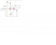
See attached - the Cathodes now has 3 Red LED's (either 7 or 9 volts bias) - I really like this pre I made...sorry for the crappy attachment - has a blue velvet 100k on front end and if I remember a 1M resistor on output.
Attachments
")
8k to 10k sounds more like Zin not Zout of the attenuator.john65b said:I believe the Lightspeed is somewheres between 8k - 10k if I remember correctly...
Actually, I think its around 7k...from the Lightspeed Forum (I asked Georgehifi about this)...
A Lightspeed or even a passive 20K pot will be around 7k ish.
That could well be right.john65b said:Actually, I think its around 7k...from the Lightspeed Forum (I asked Georgehifi about this)...
7k would indicate that each opto was sitting @ around 28K when both are at the same value and outputting -6db to the next stage.
If 28k are the -6db values, then this is the worst case and for all other attenuation levels will, just like any other passive pot, drop to lower Zout
Will the next stage like a variable source impedance on it's input and no buffer between them?
Dual Drivers
Back around page 230 there was a discussion of doubling up the drivers for more pairs of outputs or higher power. I am using 4 pairs of MJL4302/4281 outputs and 15032/33 drivers. I was considering mounting one (pinkmouse) driver board on each 2 pair heatsink to reduce output lead length considerably. Does this sound valid? Any value changes recommended? I plan to bias as high as my heat sinks will allow with +/- ~41V and a 1200VA toroid per channel. Also, if I double the driver boards only 1 should have the bias transistor populated, correct?
Bob G.
This is the circuit diagram I used to populate the Pink Mousie board.
It has yet to be confirmed that this is the latest diagram for the MkII.
Jozua and PWatts have had a quick look at the original amp and found extra components. Their Christmas present to all of us will be to trace out the original circuit soon.
I do not believe that there will be a huge difference, probably two pairs of drivers etc.
Regards
Harry
Attachments
http://www.diyaudio.com/forums/showthread.php?postid=1265968#post1265968sierrafan said:It is necessary to make that modification, supply in order to ksa-50 2X55V DC?
I want to extract 200W 4ohm class AB.
these results for a KSA100 Klone would be fairly close for a KSA50 Klone.
It indicates you do not need +-55Vdc to get 200W into 4r0.
A 35Vac transformer generating +-50.5Vdc when biased to an amp or so, will give you your 200W target.
A 6pair output stage got 257W into 4r0 from +-50.1Vdc when biased to 2.6A.
- Home
- Amplifiers
- Solid State
- Krell KSA 50 PCB