well, after installing a 25K pot across Re27, and reducing the resistance from 1.8K to 1.6K, no difference in bias voltage, being 0 volts.
i then got a little brave, and reduced the resistance to 1K. still 0 at bias (measured from emitter of Qe23 to emitter of Qe21).
hmmmm. at Re19, measured 26.3v from C15, but dropped to 8.2v on other side of Re19 leading to Qe17. is this a huge drop? anyway, i connected the same 25K pot across Re19, dropped resistance to 4K (apprx) from Re19's 4.7K. no change to bias setting.
your thoughts please, gents. chime in should any of you have a constructive suggestion.
aidan
Lets just recap over a couple of things. And no problem around Re17 and Re19 ")
The important result here is whether or not the voltage across across Qe7 varies as a result of turning the bias preset. Just looking back you have 1.9 volt that doesn't alter.
OK... And always with the bulb tester in place...
can you remove Qe9 and Qe11 and retest starting with the bias pot all back to original values and the pot again set to max. If those transistors are damaged then they could be holding the bias voltage down. The amp will 100% work normally without these as they are overload protection devices.
I'll be out for a couple of hours this morning. Try that.
Even if the bias doesn't adjust correctly you can still measure and confirm there is zero volts on the speaker outlet and retest again with a speaker. Less distortion ?
If that proves nothing then we replace Qe7 with a 2N5401 but I'm hoping this is just a leaky/zapped protection transistor that's pulling it down now.
but dropped to 8.2v on other side of Re19 leading to Qe17. is this a huge drop?
That bit doesn't sound right.
Some more readings to check so lets work back by measuring from chassis to...
1/ The positive speaker outlet terminal. That should be under 100 millivolts.
2/ The base of Qe21. That's the same as measuring on the top of Re41. Should be around 0.7 volts.
3/ The base of Qe17. Should be around 1.4 volts.
That brings us back to the your results above "8.2v on other side of Re19 leading to Qe17.
Just work back from the speaker socket with those measurements and see if/where things fall down. You can't have 8 volts on Re19 and zero on the speaker outlet. So just confirm those.
ok then. morning guys. sakis, i'll respond to mooly's points first, then attack that boards resistors.
ok, mooly
#1 a shocking -35V L, and .005 R channel
#2 again, -35.1v and top side of Re41 is -35.6, far side is -35.5
#3 -35.7v
#4 re: "8.2v on other side of Re19 leading to Qe17" okay, must be warm-up (it's warm now). the emitter of Qe17, leading to Re19 measures is now -27.4v, and the other side of resistor is +14.4v.
#5 did i mention i love tubes?
all measurements with negative lead on chassis. speakers removed. no input (set to aux.)
thanks so much guys
Last edited:
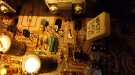
aarrrggghhhh. image too large. instead, see page 12 of 13, here
http://flipperpie.com/KenwoodKA-3500Service.pdf
http://flipperpie.com/KenwoodKA-3500Service.pdf
http://flipperpie.com/KenwoodKA-3500Service.pdf
http://flipperpie.com/KenwoodKA-3500Service.pdf
"reversed" Qe17, and played well, almost as well as the right channel, then i smoked Qe17. crap!
when it failed, it exhibited the same symptom as before. high current draw. just checked, and it is shorted.
i have another 5551, but i'll wait for some input from you experts.
remember, before it failed just now, it played very well. when it failed, the bulb lit, the current draw went up.
aidan
when it failed, it exhibited the same symptom as before. high current draw. just checked, and it is shorted.
i have another 5551, but i'll wait for some input from you experts.
remember, before it failed just now, it played very well. when it failed, the bulb lit, the current draw went up.
aidan
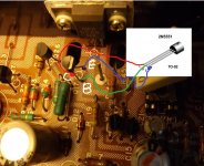
It wants rotating by 120 degrees. Like this. If you have a new one then fit that.
What about the 2N5401 ?
right. well, thats the way i just put it in, played well, then smoked
- Status
- This old topic is closed. If you want to reopen this topic, contact a moderator using the "Report Post" button.
- Home
- Amplifiers
- Solid State
- Kenwood KA-3500 and my blooper