heh, heh, that's good!
i remember walkie-talkies from the 70s. they used to have transistor wars (similar to the slew rate wars in power amps). more than a few manufacturers would solder in transistors that were not functional, but were included in the transitor count. one way i used to get parts for experiments in those days was to "repair" these devices for friends when they'd stop working.
2SB54 anyone?
mlloyd1
When I need to stick an op amp somewhere under the hood,
I use something crappy like an LM307 so that no one will
get the idea it's in the signal path. Otherwise there's usually
trouble.

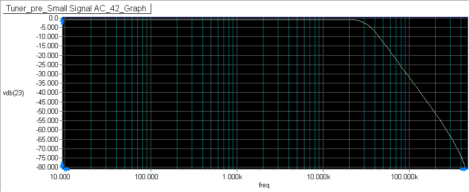
Here's the response just for the Salen Key circuit, without my pre filter. The stopband is -45dB out to 30MHz. I also ran it to 220 MHz and it stays like that.
So seems okay if you trust Spice and models and such. May be different in the real world, I wouldn't know. But, I have compared frequency reponses of my preamps with spice and they were pretty accurate though.
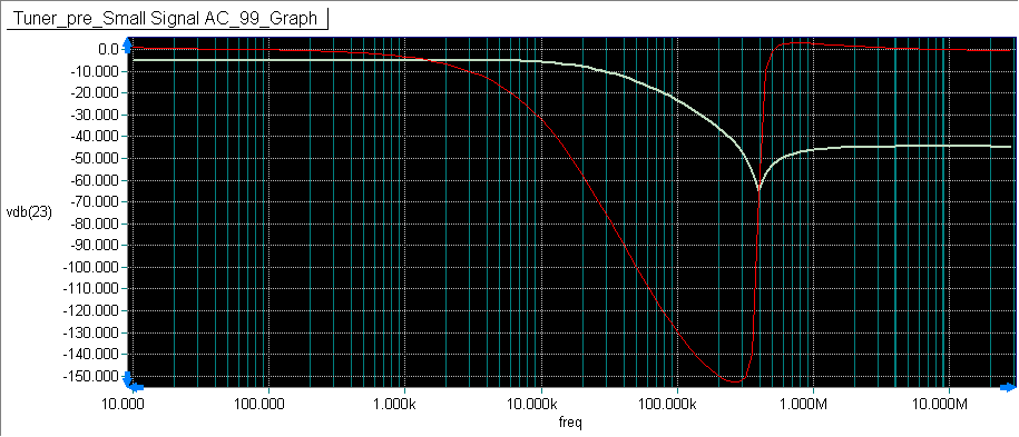
So seems okay if you trust Spice and models and such. May be different in the real world, I wouldn't know. But, I have compared frequency reponses of my preamps with spice and they were pretty accurate though.
Attachments
Before extending that into THz range, I would recommend Active filter cockbook by Don Lancaster
I doubt you are getting 50 dB isolation at 1 GHz. That's hard to do with 1/8" stainless steel. Spice isn't useful at those frequencies without getting ALL of the parasitics into it. That is usually done with an integrated system that can extract the parasitics from the layout. However I would be right behind Bob Pease on this- build it, forget the simulator.
If you are making a low pass filter for the output of a DAC (which is what is going on here I believe) there is a ton of stuff on different approaches. RF or IF feed-through isn't an issue.
If you are making a low pass filter for the output of a DAC (which is what is going on here I believe) there is a ton of stuff on different approaches. RF or IF feed-through isn't an issue.
Lets see the FM band is 88 to 108 Mhz if we over sample at 2.2 x that would gives us 237.6 Mhz noise in the system.
How do you know they're oversampling and not subsampling? Subsampling is quite common in RF, can save quite a bit on converter speed.
Before extending that into THz range, I would recommend Active filter cockbook by Don Lancaster
I already have it, did I miss something?
I doubt you are getting 50 dB isolation at 1 GHz. That's hard to do with 1/8" stainless steel. Spice isn't useful at those frequencies without getting ALL of the parasitics into it. That is usually done with an integrated system that can extract the parasitics from the layout. However I would be right behind Bob Pease on this- build it, forget the simulator.
If you are making a low pass filter for the output of a DAC (which is what is going on here I believe) there is a ton of stuff on different approaches. RF or IF feed-through isn't an issue.
Well, there is going to be a 2nd order passive filter before the Salen-Key with an Fc in the neighborhood of 30kHz. So, at 1Ghz that's going to be pretty down there in amplitude. So, I don't see a problem.
I think the big concern is around 100kHz to 1MHz and getting that down.
I'll see what I can do all passively too, but the Salen-Key helped a lot, and was much better than my first attempt at an all passive filter 4th order.
Last edited:
Which a 3 prong plug will do nothing for and just makes things worse.
se
When I listen to KDVS on my reciever,
I can hold my hand to near the chassis
and improve reception a lot.
There is a side of FM reception that
transcends any normal calculation.
I already have it, did I miss something?
Yes, stormsonic, I ignored Q, for the 2nd order active filter. I was just exerimenting with the filter as a whole, passive and active and not doing any calculations.
John
Well, there is going to be a 2nd order passive filter before the Salen-Key with an Fc in the neighborhood of 30kHz. So, at 1Ghz that's going to be pretty down there in amplitude. So, I don't see a problem.
I think the big concern is around 100kHz to 1MHz and getting that down.
I'll see what I can do all passively too, but the Salen-Key helped a lot, and was much better than my first attempt at an all passive filter 4th order.
The mistake is presuming that the caps, resistors and inductors are remotely like the indicated device at those frequencies. Few caps are capacitive at higher frequencies. Most inductors are caps at very high frequencies. And even resistors are not resistors up there. Figure every component is a tank circuit or two. The RF can easily jump around the components if there is a way. I have measured lots of filters and have seen these issues well below even 100 KHz with AC line filters. If you have the opportunity to look at construction of a WiFi module you will see very small parts and very specific layout tricks. Most of the magic is inside the chips and not visible but what is visible is done very carefully.
The challenge with an active filter is making sure the source impedance is low, zero for a Sallen-Key, to work right. This can push the previous device (the DAC) to needing high currents for the ultrasonic stuff. I prefer a resistive or inductive input. The peak currents are much lower and stress on the supply becomes lower. However suitable inductors are either big or using some ferrite or ferrous core.
It looks like your filter is 3 dB down at 50 KHz. That may be too low and affect the audio band. What frequencies are the .1 dB and 1 dB points?
Is there a specific filter requirement for the chipset? Do we know which chip is on the board? Data sheet available or is it considered "proprietary"? I hate it when these guys won't publish any useful info.
That filter does affect the audio band above 10kHz. It is just a very preliminary filter. Still messing with it. I can't anything above 9kHz anyway.
Yes, Salen - Key will work differently without a low impedance source. You make good points and I may just do an all passive filter.
A service manual and schematic is available here:
Sony XDR-F1HD Mod
However suitable inductors are either big or using some ferrite or ferrous core.
The author of the above HDR-F1HD mod mentions a ferrite bead and shunt capacitor within the tuner module, before the external 2 pole filter.
So, I think that likely takes care of any of the very high frequency stuff.
It might be best to keep the filter resistive since we don't know exactly what's in side the chip.
Also Sony's own filter uses a 470 ohm resister shunted with a 2200p cap right after the tuner module, so, I don't think it will be a problem with driving low impedance loads.
Thanks for advice, though, it helps.
John
@Johnloudb
if you want high attenuation into Mhz range, there is another approach:
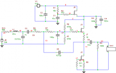
Let the fast opamp drive Sallen-Key LPF. Opamp should be removed from DC path of the signal, used only to provide feedback for filter. Take unbuffered signal from noninverting opamp input and run it through JFET buffer. Or another opamp used as buffer.
if you want high attenuation into Mhz range, there is another approach:
Let the fast opamp drive Sallen-Key LPF. Opamp should be removed from DC path of the signal, used only to provide feedback for filter. Take unbuffered signal from noninverting opamp input and run it through JFET buffer. Or another opamp used as buffer.
I think people might like my second attempt better ... I appreciate all the input.
The 20uH coil doesn't do much to the response until it's raised up to 100uH, but it could help with any high frequency artifacts. Could make it a ferrite core, if absolutely needed.
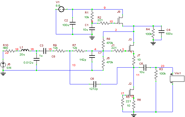
The 20uH coil doesn't do much to the response until it's raised up to 100uH, but it could help with any high frequency artifacts. Could make it a ferrite core, if absolutely needed.
Attachments
For your interest, I just published some measured characteristics of different complementary JFETs at Nelson's :
http://www.diyaudio.com/forums/pass-labs/121228-f5-power-amplifier-174.html#post2277700
As you can see, the beloved K170 / J74 are not quite complementary as we wish to think.
Vds is fixed at 9V.
Patrick
http://www.diyaudio.com/forums/pass-labs/121228-f5-power-amplifier-174.html#post2277700
As you can see, the beloved K170 / J74 are not quite complementary as we wish to think.
Vds is fixed at 9V.
Patrick
- Status
- Not open for further replies.
- Home
- Member Areas
- The Lounge
- John Curl's Blowtorch preamplifier part II