@Kindhornman
I don't really know much about American made cheeses.
Locally, we have what we call "Schwaben cheese", or "German cheese". The nearest equivalent I could find in the West was Kraft's Philadelphia Cheese. So I must have eaten tons of it many years ago, and even today, I sometimes buy it for nostalgia's sake.
There are three American originating food stuffs I dearly love and will not give up at any cost: 1) Tabasco, 2) Heinz Tartar Sauce and 3) Heinz ketchup. I'm particularly sensitive to Tabasco, I actually have a bottle in the fridge, a spare bottle in the cupboard and a third bottle in my day bag. I don't really care what's said about it, and a while ago, I was told by several people here that was the worst junk out there, but I like it and it does me good, I actually feel better after using it.
Locally, we have what we call "Schwaben cheese", or "German cheese".
https://www.youtube.com/watch?v=c7s2gW3lF-Q
I'm no expert, but the charts give the impression it's more of a cascade than a loop:
https://www.google.com/search?q=mTO...=JLX0U9yTMKXw8AGClIGAAw&ved=0CCoQsAQ#imgdii=_
Sorry if I sounded harsh keantoken and thank you for these very informative posts.
I am no expert either. My question wasn’t addressing you. It was figurative speech just to invoke some thinking about our organism.
Every connecting line in such diagrams hides at least one negative feedback path, usually two fb functioning paths, one negative and one positive. True, these communication channels are specialized, i.e. of very low bandwidth but the nesting is tremendous.
How such complex constructions withstand such abuse from our careless way of living and still functions flawlessly or at least functions?
And in sharp contrast to these, how do we make a huge case out of an amplifier with one-two intentional and another couple or two of unintentional fb loops that only needs a small deviation from it’s normal operating parameters to start operating erratically or just burst into oscillation and start smoking?
Prose off
George
know what you mean
Reminds me of my recent hospitalizations for cancer & peritonitis/bowel perforation, wherein I was strictly NPO on iv drip ONLY and was chastised for wanting to chew on ice chips. The attending ordered a cat scan with contrast to evaluate my intestinal tract after re-obstruction and puking bile ; the nurse then presented me with a QUART of contrast fluid to choke down within 20 minutes prior to the procedure.
What part of NO ORAL INTAKE did THEY not understand???
John L.
I know. Apparently, everybody is different. My doc used that formula as well..
I'll never forget the doc at that test. "Let us know when you can't go any longer".
When I could not go any longer (sustained 185), I said so...they then injected the contrast then said "go another minute".
WHAT part of the phrase "can't go any longer" did they not understand???:eek: As a former runner, the plan was always to synchronize "can't go any longer" with AT THE FINISH LINE.. (sometimes that plan worked...sometimes it didn't)
jn
Reminds me of my recent hospitalizations for cancer & peritonitis/bowel perforation, wherein I was strictly NPO on iv drip ONLY and was chastised for wanting to chew on ice chips. The attending ordered a cat scan with contrast to evaluate my intestinal tract after re-obstruction and puking bile ; the nurse then presented me with a QUART of contrast fluid to choke down within 20 minutes prior to the procedure.
What part of NO ORAL INTAKE did THEY not understand???
John L.
You wish!
Really, it's just fully skimmed cow milk cheese, turned into a paste.
However, all else being equal, a higher voltage dual power supply is better than a lower voltage one. We usually start with +/- 30V from a remote location and step it down slightly with a final power supply buffer on each stage.
My line stage and passive RIAA, way back in time, used +/- 24vdc with local reg. Use as much voltage as you can.
Here is THD from a 'simple' 4 transistor circuit I am playing with and studying at different PS voltages. .18v in and 1 volt rms out into 100K load....1KHz --
+/- 12v = .14%
+/- 15vdc = .003%
+/- 18v = .0015%
+/- 24v = .00045%
Remember when I showed/demo'ed the transistor C decreased with PS increase?.... and that it was the cause of most distortion in that topology? Here is another example.
Dont remember? ... I think it was in the CFA forum.
THx-RNMarsh
THx-RNMarsh
Last edited:
As much voltage as you can will have to stop somewhere. I rather not have it stop by seeing the cones of my drivers fly through the room.
Otherwise put, I do understand the argument for high overload margins in a phone amp, but at the same time, where are you going to loose the excess voltage that would otherwise destroy your drivers? My sense is, that it is best to limit dV/dt right at the source, which in this case is the phono amp. No need for extreme voltages there, just have adequate low pass filtering early enough in the chain.
Otherwise put, I do understand the argument for high overload margins in a phone amp, but at the same time, where are you going to loose the excess voltage that would otherwise destroy your drivers? My sense is, that it is best to limit dV/dt right at the source, which in this case is the phono amp. No need for extreme voltages there, just have adequate low pass filtering early enough in the chain.
dvv,
We call that cream cheese here in the states and Kraft/Philadelphia brand is probably the best known of all. Goes great on a bagel with smoked salmon and onions and even a tomato. Lox and bagels, oh my. As for the Tobasco sauce of course that is in the cupboard along with a rash of other hot sauces and of course Tapatio sauce which is what my kids want. We do eart lots of spicy foods here in California.
ps. Cream cheese is the basis of all cheese cake deserts and Philadelphia brand is number one in that regard.
On the subject of power supplies for an amp or preamp where you want dual voltages what is the preferred method to produce those voltages? Do you use one power supply with an elevated output voltage and step it down for the lower voltage or would you use two separate supplies , one for each needed voltage? Can someone show a simple schematic of one of these dual voltage power supplies.
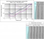
You wouldn't expect it to overload. The biggest subsonic peak is at the arm-cartridge resonance (~10Hz). That's about 40dB down from the reference, which is +12dB from nominal (in the left figure). So the LF cartridge signal is -28dB from nominal.
Let's plug in an MM with a 5mV nominal output. Assume that the MM preamp has a normal gain structure with 50dB of gain at 1kHz. At 20 Hz, gain will be about 70dB. The LF signal is roughly 0.2-0.3mV, corresponding to about 0.6V out from the preamp. Not very challenging!
All correct and thank you for taking the time to do the calculations.
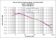
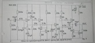
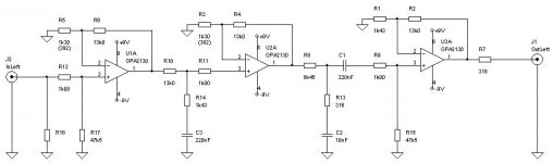
One of the preamplifiers I had built during 1990 was a clone of Naim NAC-32.
The MM RIAA circuit of this pre had the code NA322. That was (and still is) a fine circuit.
I had measured it then, found my notes and drew some plots. You will notice that it has an issue with overloading , particularly at LF.
For comparison, I plugged in the measurements from Hagerman Bugle 1 MM RIAA that I built some 10 years later. It too is sensitive to overloading but not that much. Additionally I have shown the change of input overload with psu voltage for this preamplifier.
There are 2-3 more SS preamps I built back then with different topologies. I’ll look deeper and see if I can show some measurements of them.
George
Attachments
Tapatio sauce which is what
you realize,
'tapatio' places one in a particular social/economic/ethnic class/situation.
much better -
http://www.walkerfoods.net/products.html
http://www.empacadorasanmarcos.com/
your own brand -
http://www.brandedsauces.com/branded_sauces.htm
Last edited:
No. It’s Tics and pops (and high modulation velocity signal) over LF
And you are not asked to believe.
Just test it with your system.
With my system, here is what I can show you.
There is some 20-27dB of subsonic signal that the pre had processed in addition to the intended sonic signal (and still not overloading
George
George,
That LF stuff looks like arm resonance and after processing on the RHS panel, it's still there. Am I reading the graphs right?
> 'tapatio' places one in a particular social/economic/ethnic class/situation.
Likewise 'pato' :
Urban Dictionary: pato
Likewise 'pato' :
Urban Dictionary: pato
After thinking a lot about EMI stuff, I've been thinking about a way of reducing ground loops on a test bench or desktop computer, and even audio systems.
It's really simple. Any excess cable tends to form large loops hanging everywhere messily. What you can do is fold the cable in half and twist it. This minimizes it's inductance and coupling to external fields. This way you can get as close as you can to direct wires from place to place. If many cables come from the same appliance, they can all be twisted together and run in one big bundle. For instance all your test equipment power can be run in a twisted bundle to the power strip, with extra lengths of wire twisted as above if necessary. This reduces the potential ground loop errors and emissions. If you're using a wall wart with an excessively long cord on the test bench, you can twist the wire so the excess hangs harmlessly without catching or wrapping around anything and the rest of the wire goes directly to the point of use.
Even without the benefits in EMC, I like this idea because it really gets the cables out of the way without them causing random accidents.
So my question is, how much of a real benefit to EMC do you think this has in an ordinary test bench?
- Status
- Not open for further replies.
- Home
- Member Areas
- The Lounge
- John Curl's Blowtorch preamplifier part II