The capacitance is odd however, the proximity to the bench reduced it? Weird. Is it possible that whatever you used to hang the cable introduced capacitance?
jn
I forgot to answer the capacitance question. For the free air test it was connected to the fixture at one edge of the wooden bench top. The other end to the edge of an adjacent bench. Three foot clearance all around.
Dave
Thanks Fitzfish. I think you are on to something!
My pleasure. The question has long attracted me for a non-audio application but it is interesting to ponder in the context of speaker cables. Need to figure out how to characterize a few to see if cable Ls changes significantly with current. If it changes much using sine wave excitation into an LCR instrument di/dt step induced field changes could be well worth exploring as JN alluded to some time back.
Dave
I don't have the tools to change a bit point angle. But I can buy more bits..
BTW, I can only pot with a hardener which has a glass transition temp of 45C. That limits the max CVR temp to about 60C.
Look around the shop for a grinder with aluminium oxide (white) wheel ( for steel bits of course )
Why it has to be epoxy potted if you plan to operate the CVR under some power ?
Can’t be made to be immersed in oil? (A cylindrical can. In, Out at the bottom and top surface of the cylinder, the can filled with oil).
I also have D and Q (fewer points with Q as I did it after the original measurements) if interested.
Dave
Thank you in advance 😉
George
That preamp didn't use any output transformers. Direct coupled output with a servo. And this in 1977.
Dave
Thank you in advance 😉
George
Very welcome George.
Attachments
I have a pair of 4284A's...mebbe if I stack em??
Seriously though, I'm making fixturing to wind some #10awg inductors for Ls/Rs testing, I'll also use a good CVR and my rmx1450 with some dummy series load to keep the amp stable.. I don't know if it'll be good enough for just a cable measure, I was gearing it towards an inductor of between .3 and .5 mH.
jn
Sent you an email with a few equipment questions.
Dave
Heatsinks are grossly overrated.
Please elaborate .
I find Berning's patent on P channel Fet and tube combo quite interesting.
I find Berning's patent on P channel Fet and tube combo quite interesting.
You may want to take a look at the next issue of Linear Audio.
Is that a sales pitch for the mag?You may want to take a look at the next issue of Linear Audio.
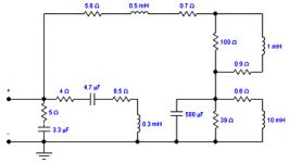
Has anyone in the pass thousand years or so developed an electrical model of a speaker which includes the nonlinear back emf generator? Not a mathematical model... an electrical model so we can use it as a load on amplifiers.... for SIM use???
THx-RNMarsh
THx-RNMarsh
You may want to take a look at the next issue of Linear Audio.
"In his Equal Opportunity phono preamp article, Stuart Yaniger offends tube and solid state aficionados alike".
Jan
Last edited:
I'll stick with my own consul for phono design. '-) Sorry, thank you everybody.
Last edited:
"... offends tube and solid state aficionados alike".
So basically everyone. What´s the news ?
So basically everyone.
That is my goal in life. 😀
After 40 years, it's time that someone updated Berning's work. It was too clever to be allowed to remain dormant.
Stereophile published this - Real-Life Measurements | Stereophile.comHas anyone in the pass thousand years or so developed an electrical model of a speaker which includes the nonlinear back emf generator? Not a mathematical model... an electrical model so we can use it as a load on amplifiers.... for SIM use???
THx-RNMarsh

Dan.
Last edited:
- Status
- Not open for further replies.
- Home
- Member Areas
- The Lounge
- John Curl's Blowtorch preamplifier part II
