"In his Equal Opportunity phono preamp article, Stuart Yaniger offends tube and solid state aficionados alike".
Jan
Ohh, ok, daily ritual now in print .....
")
Please elaborate .
Many people think highly of Mr. Carver, but fail to accept that the products he designed at young age were seriously flawed.
In retrospective, several Carver amps are prime examples of how it should not be done.
(afair, Mr. Bob Carver turns 70 this year)
And this in 1977.
And an MSRP of $1500.
If Mr Berning were to manufacture today, his product would likely be in excess of $10k, and he'd stand a chance of being ridiculed for catering to a fashion business.
(I sniff panties, the second the subway door opens)
Has anyone in the pass thousand years or so developed an electrical model of a speaker which includes the nonlinear back emf generator? Not a mathematical model... an electrical model so we can use it as a load on amplifiers.... for SIM use???
THx-RNMarsh
To include everything it would be non-minimum phase and include frequency dependent values. I'm sure there is a good start somewhere in the JAES but I don't get it for free.
And an MSRP of $1500.
If Mr Berning were to manufacture today, his product would likely be in excess of $10k, and he'd stand a chance of being ridiculed for catering to a fashion business.
(I sniff panties, the second the subway door opens)
The mechanical side of things probably lacked the most 40yr. ago. Now half the BOM would be the machined billet, knobs and connectors to keep up appearances.
And an MSRP of $1500.
If Mr Berning were to manufacture today, his product would likely be in excess of $10k, and he'd stand a chance of being ridiculed for catering to a fashion business.
Cheaper, probably- much of the expense was the switching power supply, which (because of the era) was all-discrete.
At the time, I was working with Precedent Audio, the distributor. Until the rave Stereophile review, Precedent had a tough time moving them, and (indirectly) it was because of that power supply. The preamp was a featherweight, and the fashion buyers were put off because of the lack of mass.
The TF-10 had strong points and weak points. It was no distortion champion and it was pretty noisy. Bandwidth of the tube-FET stages was quite good, though, and the tube life was outstanding. Like most other Berning products, it was way ahead of its time. I still have one in my lab.
I have that as well as diamond, use it to sharpen hardened gravers.Look around the shop for a grinder with aluminium oxide (white) wheel ( for steel bits of course )
Why it has to be epoxy potted if you plan to operate the CVR under some power ?
I spent 4.5 years in a milspec production line arena, all we did was epoxy encapsulate mil bridges. Figured I'd actually use knowledge and experience for a nice change of pace.
jn
Has anyone in the pass thousand years or so developed an electrical model of a speaker which includes the nonlinear back emf generator? Not a mathematical model... an electrical model so we can use it as a load on amplifiers.... for SIM use???
THx-RNMarsh
I am not aware of one. How would it model the frequency dependent eddy dissipation and proximity effects in the vc/gap/iron/inductors/capacitors?
jn
ps. George, Demian, thanks. I received both, no sleeping tonight...
Last edited:
Thank you Dave for posting your measurement results.
The Ls plot seems OK to me but the Rs plot doesn’t fit the scenario of eddy current induced at the nearby metals. The D plot does fit this scenario.
The C plot is indeed strange. Proximity with metal should raise the capacitance of a cable. This is known and verified from metal shielding RF circuits and components.
I am starting to suspect that within the “Three foot clearance all around the free hanging cable” there was an invisible alcladed Martian keeping notes of your strange -for a human- behaviour.
Oh boy. There are so many things that have to be characterised just for to do a bunch of measurements. I hope you don’t take it as an offence.
You can tease me as much and harder when I will start posting my plots.

George
The TF-10 had strong points and weak points. It was no distortion champion and it was pretty noisy. Bandwidth of the tube-FET stages was quite good, though, and the tube life was outstanding. Like most other Berning products, it was way ahead of its time. I still have one in my lab.
Just read the patent, so the distortion cancellation claims are exaggerated? Seems an NFET in place of the tube would reduce the resistor and it's noise and retain the self bias.
Many people think highly of Mr. Carver, but fail to accept that the products he designed at young age were seriously flawed.
In retrospective, several Carver amps are prime examples of how it should not be done.
(afair, Mr. Bob Carver turns 70 this year)
I have alot of respect for Bob Carver , but junk is junk, just saying ...
To give you an idea, the line stage of the preamp has about 0.2% THD at 2V out. Not terrible, but not great.
That's what you get roughly with an SK170/SJ74 pair at 100mV p-p by quick sim. For a 26dB gain stage that's, give or take, the same answer. So the question is why the valve?
This is not entirely true.Dutchie,
Berning stuff was highly rated, i was not aware of any negativity surrounding his products and 1500 was not expensive , even in 77, McIntosh and Levinson for eg. were much pricier, as Koetsu, to name a few ..

Levinson's most expensive version 'D' of JC-2 preamp is listed in April 1976 issue of Audio at $1175, standart at $1050.
McIntosh preamps were $449/$749 at that time according to this site:
classicaudio.com..... All About..... McIntosh
Attachments
Last edited:
I was refering to using them in Mr. Berning's circuit where there is no cancellation of seconds. He essentially uses 1/2 of the self biased complimentary diff-pair you show and then uses only 1/2 the output. Still for it's day probably worked a lot better than vintage 1970 op-amps.
That's what you get roughly with an SK170/SJ74 pair at 100mV p-p by quick sim. For a 26dB gain stage that's, give or take, the same answer. So the question is why the valve?
Some people love tubes.
David (and Murray Zeligman, the owner of Precedent) were convinced that the tube circuit sounded better than a FET equivalent. Of course, just a few years later, Murray and I were doing FET-only circuits for MC headamps...In your FET sim, what did the distortion spectrum look like? I may breadboard it to check the spectrum against model. The tube-FET version was nearly all second, as you might expect.
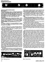
edit: For those who are interested in audio history, the schematics are here: http://davidberning.com/support/tf10
This is not entirely true.
Levinson's most expensive version 'D' of JC-2 preamp is listed in April 1976 issue of Audio at $1175, standart at $1050.
What were the prices in the late '70s? You might recall that we were in a hyperinflationary period then, and 2-3 years was a big difference. The main competition was things like Audio Research SP-3/3A/6/6A. The TF-10 was far from the most expensive preamp in the shops. At release, it was about $1200 in the US.
This is not entirely true.
Levinson's most expensive version 'D' of JC-2 preamp is listed in April 1976 issue of Audio at $1175, standart at $1050.
McIntosh preamps were $449/$749 at that time according to this site:
classicaudio.com..... All About..... McIntosh
look deeper
C-29 Preamp
1978-1984
1399.00
C-32 Preamp
1977-1981
1649.00

- Status
- Not open for further replies.
- Home
- Member Areas
- The Lounge
- John Curl's Blowtorch preamplifier part II