I just cannot get anywhere with this without being deluged with extraneous input. Sorry.
John, even I figured it out in a short time --- this is a social medium type place. On other threads and forums, the moderator kicks your comments off if you dont stay on the subject. Not here... 'cause its basically a social outlet for designers and friends. Have a drink, my friend. It's OK.
THx-RNMarsh

You should see and hear my LATEST quantum products!
One can either see OR hear a quantum product.
Not both at the same time..
jn
Thanks George and kindhornman for the tips.JN,
Don't use a carbide drill on copper use plain steel. Also it may help to actually dull the drill a bit so it doesn't grab and break. Same goes for turning soft copper if you ever try that, mild steel and a dulled edge works best.
That just made me realize, I've been working brass for my antique clock repair stuff. duh.... I've some great experience working brass.
There's no reason not to use brass plates instead of copper...
jn
Thanks George and kindhornman for the tips.
That just made me realize, I've been working brass for my antique clock repair stuff. duh.... I've some great experience working brass.
There's no reason not to use brass plates instead of copper...
jn
If you still want to source copper pick up some Tellurium Copper. That half a percent Te in the C14500 alloy makes a lot of difference while machining.
Dave
Thanks for the reply George.
The GR 1689M I have is nice old bench instrument with 0.02% basic accuracy. Even with an instrument of this caliber, re-calibration at each frequency point is required to get reasonably accurate and repeatable results since these measurements are at the bottom of its range. Noise and the limited resolution also matter down there.
Understood and agree. The 1689M in this case is connected to a fixture via 4 coax cables. Open and zero calibration is performed at the same place on the fixture where the test cable connects to eliminate these additional errors.
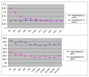
I was fishing a bit to see if there was some experience with proximity or other parasitic effects to a cable under test beyond the normal error sources. Attached are a pair of graphs showing the Ls and Cs per foot of an old ~9awg cable measured in free air vs. sitting on top of a wood and metal bench.
Dave
This is my experience with cheap LC meters too.
For L measurements at the low scales on cables, I get a rather broad range of readings say +/- 10-20% of the calculated expected value and this with only some instruments, while for C measurements the range is much narrower~ +/-2-3% with all instruments.
Excellent point. The setup parasitics may not be viewed identically at every frequency, so this is an additional error source if not compensated for.
The GR 1689M I have is nice old bench instrument with 0.02% basic accuracy. Even with an instrument of this caliber, re-calibration at each frequency point is required to get reasonably accurate and repeatable results since these measurements are at the bottom of its range. Noise and the limited resolution also matter down there.
To quote:
"inductance can only be properly understood if it is realised that it is only defined for a closed circuit.
What is usually meant by a statement about inductance is incremental inductance, such as that
caused by a length of wire if it were to be inserted into a closed circuit."
Parasitic means additional entities there by accident. When the test leads or fixturing have their own inductance and that inductance is significant compared to the desired measurement, it needs to be considered. If you clip the test leads together, you will measure the parasitic of the leads.
Understood and agree. The 1689M in this case is connected to a fixture via 4 coax cables. Open and zero calibration is performed at the same place on the fixture where the test cable connects to eliminate these additional errors.
I was fishing a bit to see if there was some experience with proximity or other parasitic effects to a cable under test beyond the normal error sources. Attached are a pair of graphs showing the Ls and Cs per foot of an old ~9awg cable measured in free air vs. sitting on top of a wood and metal bench.
Dave
Attachments
Jn will come and provide his valuable comment on this.
My side-comments: If higher current increases the network losses, measurement system’s noise figure will worsen.
I want to hint on the –measuring instrument dependent-risk that the resulting higher voltages at the input of the instrument may increase intermodulation distortion products. This effect is not as easily verified as the effect of input overloading, which may also occur.
I would suspect linearity with level. If metals with permeability are involved, then the BH curve will introduce level dependent changes.
jn
Would be interesting to test. The only commercial instrument I am aware of that could test this is an HP 4284A with a 42841A 20A bias generator (or two) added. I believe either the available fixture or the high current cable for the 42841A would have to modified to test cables. Just an educated guess as unfortunately I don't have such a beast available.
I'm not sure if the high current RCL "transformer" meters have a low enough Ls range work here...
Dave
I was fishing a bit to see if there was some experience with proximity or other parasitic effects to a cable under test beyond the normal error sources. Attached are a pair of graphs showing the Ls and Cs per foot of an old ~9awg cable measured in free air vs. sitting on top of a wood and metal bench.
Dave
A rise in inductance at the lower frequencies is certainly indicative of a metal benchtop with permeability to enhance the field.. So I would expect the metal to be magnetic. At the hf end, I would have expected a drop as the metal began to exclude the magfield.
If you repeat but use Ls/Rs, I suspect you'll see Rs increase at the upper frequencies. If you feel like doing it, that'd be great.
The capacitance is odd however, the proximity to the bench reduced it? Weird. Is it possible that whatever you used to hang the cable introduced capacitance?
jn
Thanks Fitzfish. I think you are on to something!
Gee John,
In the last decade of our repartee, you've never thanked me for anything.
Another decade or so of this treatment, and I may begin to think you don't like me.
")
jn
You will never understand the power of perfume unless you have been in the Paris Metro with a young woman who knew how to select her perfume properly to match her own scent.
Now you're starting to use the right analogies for this high end audio business . . . Keep it going and you'll start to draw the right conclusions
Would be interesting to test. The only commercial instrument I am aware of that could test this is an HP 4284A with a 42841A 20A bias generator (or two) added. I believe either the available fixture or the high current cable for the 42841A would have to modified to test cables. Just an educated guess as unfortunately I don't have such a beast available.
I'm not sure if the high current RCL "transformer" meters have a low enough Ls range work here...
Dave
I have a pair of 4284A's...mebbe if I stack em??
Seriously though, I'm making fixturing to wind some #10awg inductors for Ls/Rs testing, I'll also use a good CVR and my rmx1450 with some dummy series load to keep the amp stable.. I don't know if it'll be good enough for just a cable measure, I was gearing it towards an inductor of between .3 and .5 mH.
jn
Now you're starting to use the right analogies for this high end audio business . . . Keep it going and you'll start to draw the right conclusions
Don't tell me your wife stops at the Lancome counter...
their Visionnaire Range which contains a patented ingredient, "LR 2412", aimed to improve skin texture qualities, especially in pore reduction, fine lines and uneven skin tone.
while the latter turns any old hag into a luscious beauty for about $300 a bottle of rose water.
There's always worse.
( http://i-cms.journaldesfemmes.com/i...re-nouvelle-ambassadrice-de-l-oreal-paris.jpg )
A rise in inductance at the lower frequencies is certainly indicative of a metal benchtop with permeability to enhance the field.. So I would expect the metal to be magnetic. At the hf end, I would have expected a drop as the metal began to exclude the magfield.
If you repeat but use Ls/Rs, I suspect you'll see Rs increase at the upper frequencies. If you feel like doing it, that'd be great.
The capacitance is odd however, the proximity to the bench reduced it? Weird. Is it possible that whatever you used to hang the cable introduced capacitance?
jn
JN,
Your analysis on the bench materials is just about spot on. It is a wooden door top over a steel frame. There is a steel drawer set under the area where the cable was sitting for the test. Perhaps the distance on the HF end contributes to the lack of rise at the high end. The cable is the star quad alluded to earlier.
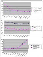
Easy to oblige as I recorded all of the data at the same time. I also have D and Q (fewer points with Q as I did it after the original measurements) if interested.
Dave
Attachments
Last edited:
What about a tube phono stage with Jfets .....
You're about 40 years late.
Tube amplifiers for high-end audio by The David Berning Company

- Status
- Not open for further replies.
- Home
- Member Areas
- The Lounge
- John Curl's Blowtorch preamplifier part II