nigel- if I understand what you have said you have a choke in the earth line. Is that right?
If so then it is probably an earth loop you had, which the choke would break.
I prefer the diode bridge "earth disconnector" idea, which has worked well for all the amps I have built.
Probably a topic for another thread, except to say that it is a generic solution that also would work for the JLH design in this thread.
amplidude- are those heatsinks from an old force cooled unit? If so they need to be mounted vertically - or have an airflow through them (which adds a noisy fan).
IIRC they were insulated in the original mounting, but as Nigel pointed out if you can keep them insulated you can mount the transistors directly, (still with thermal grease though) which keeps the thermal resistance low.
And I agree, it is transistor temperature which determines lifetime. The cooler the better!
I bought them from an old ham amateur, it was a gigantic power supply, and yes they are to be mounted in a tunnel with a fan, I have all the bolts and insulators somewhere,amplidude- are those heatsinks from an old force cooled unit? If so they need to be mounted vertically - or have an airflow through them (which adds a noisy fan).
IIRC they were insulated in the original mounting, but as Nigel pointed out if you can keep them insulated you can mount the transistors directly, (still with thermal grease though) which keeps the thermal resistance low.
And I agree, it is transistor temperature which determines lifetime. The cooler the better!
I do like the direct mount approach, I will give it a try, pretty easy when using to-3 sockets.
I thought of a bath of water once and water pump. Turn the bias up and water on. Water needs to be forced to flow to work best.
Lister industrial engines worked this way. Big water tank that was kept full.
Water and electricity needs thought. A kettle works. As the energy would be wasted to the air it's not a new factor. Although not cheap energy the heat could be used.
.
Lister industrial engines worked this way. Big water tank that was kept full.
Water and electricity needs thought. A kettle works. As the energy would be wasted to the air it's not a new factor. Although not cheap energy the heat could be used.
.
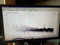
And here are two arta measurements, again at 1 amp bias and 1 volt rms across 4r7 resistor, 1khz and 10khz, I'm sure I can lower the noise floor more with better cable dressing and maybe crank the bias higher, but the outputs got alarming hot, still only using two outputs, and the insulators were some old I had laying around, I ordered some new ceramic insulators and to-3 sockets, do any of you have experience with the ceramic insulators??
I saw two different thicknesses 1mm and 2mm, I went for the thinnest, the thick are some ussr army leftovers, the dealer said they might be berylium oxide, I've heard it should be a great heat conductor.
Ps. Tried also same with 500nf, THD was unchanged.

I think everything looks fine for stability (others, please correct me if I'm wrong). Seems to be a lot of PSU ripple in the FFT. I have mostly been using switched PSU's or bench supplies for my JLH experiments, so they looked a lot cleaner, which means I have no idea how much PSU ripple is acceptable in the FFT. I never measured distortion with the cap across the load..
You could try the two-tone and multi-tone signals in ARTA too to get more on IMD. I actually like them better. I just check the single tone to get an idea of the distortion spectrum, but I think multi-tone says something about the 'distortion floor' similar to when it's playing music.
The heat sinks in the picture look very small.. I have done short tests with small heat sinks, but they overheat quickly, and time flies when playing around with measurements, adjustments etc.. Suddenly they are overheating.
Hi rally.
I must admit that I'm not all that into arta, is it in generator settings you find multitone,
Yes, generator, you have the scroll down menu in the upper left of your screen. You can go in to generator settings too if you want to specify your own frequencies for single or dual sine. Multitone is fixed as far as I can remember.
Yeah, looks like a lot of noise. Hopefully you can improve it when you finish your amp. Is it external or from PS? You can short the input terminals on the amp, if it's still there it's from the PS. Maybe some extra RC filtering to the low power part of the amp (everything except output transistors) could help if it's ripple from the PS. I think I did some sims on that earlier.
You can also try loopback on your sound card to see how much 'dirt' you have in that part of your setup.
Last edited:
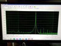
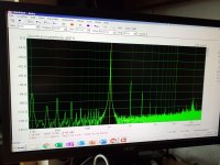
Have been working on reducing all of that noise showed on arta, the results shown in pics.
First pic is 1 khz looped back into soundcard, noise floor is okay.
Second pic is 1khz 1 watt much nicer than before, theres still alot going on in low frequency, with 1a bias theres 40 milivolt ac on rails, 3rd harmonics are better also
First pic is 1 khz looped back into soundcard, noise floor is okay.
Second pic is 1khz 1 watt much nicer than before, theres still alot going on in low frequency, with 1a bias theres 40 milivolt ac on rails, 3rd harmonics are better also
Attachments
Now you are getting somewhere ")
You can average measurements to get the noise floor down a bit, but the distortion peaks are not drowned in noise, so it's not really needed in this case.
You can also change the windowing from Hanning to Kaiser7 or similar to get better resolution in the graph (you will see what happens when you change)
You can try to optimize the output and input levels to have as low distortion as possible in loopback.
Hi.
Those advices you gave paid out, and I did play around in arta to familiarize myself with it.
I tried bf872 bf872 as drivers also but the sinus waveform got thick, I cured it with 100pf collector to ground now it made nice sharp waves, it's a very fast driver low cob, but collector max current is only 0.03 amps, to low I think.
I'm happy.
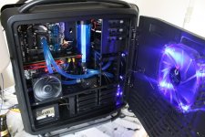
Today is made one channel with all four outputs, and back to the original drivers, I didn't expect much sonic difference, I got bias set, and DC offset, and plugged my speaker to it,
Man what a difference, much more depth, bass was much more present, I actually had to lower the equalizer settings, way to much bass, after that, well can only say it's the best amp I ever owned, and it's still mono, it's a keeper and worth a expensive chassis.
Next step will be the power supply, have been looking at the capacitance multiplier at soundau.com, ripple should get as low as a few Mv.
Good! A hobby should make you happy
It could be better (or at least cheaper) to look at improving PSRR of the amp first, before going crazy with the power supply? I looked at this a little(simulation), but there are others with more experience of linear supplies with these amps. I know it's not easy to find something in this thread, but there should be something somewhere..
I was thinking the other day, that maybe back to back diodes between transformer center tap and rectifier caps center point would allow limited DC floating of the ground to avoid DC on the speaker while warming up. The dual supply version I tried (same one as amplidude) had more than 100mV offset at startup, slowly going toward zero while heating up.
Yes very rewarding hobby indeed.
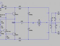
I was looking at the scheme below, I found it in pass f5 thread, and promises very low ripple, plus I have all parts already, I will study thread and schematic some more,
Your idea with diodes is unfamiliar to me, could you draw it up real quick with whatever is easiest
I was looking at the scheme below, I found it in pass f5 thread, and promises very low ripple, plus I have all parts already, I will study thread and schematic some more,
Your idea with diodes is unfamiliar to me, could you draw it up real quick with whatever is easiest
Attachments
Something like this. Transformer to the right.
It should allow the ground to float within certain limits (voltage drop over diodes) which should be enough to cover the voltage offset seen on the output.
I'm not absolutely sure it works, but in my imagination it should, even though I have not fully thought it trough.. It would require separate grounds&capacitors (C6,C7) and diode pairs for each channel though. No problem with 2x mono setup. I'm sure somebody smarter can say yes or no really quick
Are you using separate transformers for each channel, or the same?
Attachments
- Home
- Amplifiers
- Solid State
- JLH 10 Watt class A amplifier