Hello Nigel,
Many thanks for that good of you. I was going to spray the back tomorrow I'll leave it now. I've got some Solvol Autosol somewhere I'll polish it with that.
Cheers.
Against a piece of glass if you can. If it isn't flat something more aggressive like silicon carbide paper.
Are you going to use ally angle to mount transistors. If you are I would strongly advise to lap the ally angle to the heatsink. I started with valve grinding paste and ended with solvol. Then bolt the angle on very firmly with a good paste between the two. I found this to be quite important to best dissipate the heat.
you may not need to use a capacitance multiplier on the output power stage; in my version of this amplifier of which there is a thread somewhere called TGM10 I simulated the amplifier with a capacitance multiplier only on the front end and it gave all the benefit for PSSR whilst leaving the power stage free to do its thing
I had to try a quick simulation on the CCS version, with linear dual supply on the outputs, and separate DC supplies to the front end. For some reason the ripple on the output was a lot worse with the separate DC to the front end: 150mV vs 5mV.. Ripple voltage from the linear supply was abt 0,3V in both cases.
Seems to be some cancellation of the ripple going on with the double CCS front end like the one amplidude has.
I (think I) remember that I simulated RC-filtering the front end supply on the 69 JLH (bootstrap, no CCS), and that improved the PSRR. CCS seems to behave different.
Last edited:
I'm thinking I did something wrong in my simulation.. The ripple on the positive and negative rails should be 180deg phase right? I had them in the same phase, and that seems to change things a bit.
I'm confused.. maybe they should be the same phase anyway..
I'm confused.. maybe they should be the same phase anyway..
Last edited:
Look at MOSFETs in multiplier circuits. They are fast and ideal in many ways. T0247 sizes exist and can be low cost. Sometimes MOSFETs give slightly more second harmonic distortion. This says that the multiplier is an amplifier also. A hybrid device in complimentary pair might work. JLH class AB amplifier had that. That is bipolar input and MOSFET drain output. Linear fast and cheap PSU needs to be faster than the amplifier.
My condolences, it must have been painful, lost my mother e few years back, such a empty feeling, I'm sure your brother would have alot to contribute with here.I would guess up to 1/2 watt it's ok. Remember the speaker cools itself at modest levels if the magnet or dust cap is ventilated. That also reduces distortion. The second harmonic I refer to is speaker distortion. Most speakers will be noticeably different if second harmonic reduced. Faster sounding and often better if so.
I had a little Russian TV called Rigonda. It had a SE class A amplifier with no output capacitor. The DC offset was considerable. The speakers engineered to centre! I without thinking connected my perhaps Whafedale Lintons to the TV. My brother was horrified. It worked for weeks quite alright. The more remarkable thing was he was 10 and already knew about SE class A.
Simon died a few years ago from a mystery virus rather like now. Such a shame he never joined DIY Audio. He made complicated things easier to understand. I have all his test gear.
I found a capacitor multiplier made by scafas, a member here, its bought and paid, saved me from prototype board, they always end up looking like some fancy modern art

Thank you for saying that. I sometimes write him an email hoping it keeps the address alive. I don't know the password so have no idea. I limit myself to. " In the unlikely event you can read this".
When ever I have problems to solve I find it easy to pretend to be him. You know that works! He was incapable of being incorrect. Sometimes that would mean he didn't have an answer. I have an answer for everything and I am not always right.
When ever I have problems to solve I find it easy to pretend to be him. You know that works! He was incapable of being incorrect. Sometimes that would mean he didn't have an answer. I have an answer for everything and I am not always right.
Hello,
Thanks for the advice Tony and Nigel I did use some wet and dry paper before the Brasso (no Solvol) my goodness that brought up a shine. I'm waiting for some Aluminium strip that I can cut up to 75 x 40 mm and use to mount the TIP3055's. Further back in the thread I found that attaching TIP's like this would dissipate the heat more efficiently.
I bought some Aluminium angle to hang the heatsinks on and started on my box its about 12" x 17".
I'm wondering now, having only just thought about it if I need a pre-amp, I'm going to make the JLH 1969 version. My input thingy is an LG DVD/CD player £35.00 will play anything and makes my modded CD723 which refuses to play anything I create myself sound like Monty Python's Parrot.
Cheers
Thanks for the advice Tony and Nigel I did use some wet and dry paper before the Brasso (no Solvol) my goodness that brought up a shine. I'm waiting for some Aluminium strip that I can cut up to 75 x 40 mm and use to mount the TIP3055's. Further back in the thread I found that attaching TIP's like this would dissipate the heat more efficiently.
I bought some Aluminium angle to hang the heatsinks on and started on my box its about 12" x 17".
An externally hosted image should be here but it was not working when we last tested it.
I'm wondering now, having only just thought about it if I need a pre-amp, I'm going to make the JLH 1969 version. My input thingy is an LG DVD/CD player £35.00 will play anything and makes my modded CD723 which refuses to play anything I create myself sound like Monty Python's Parrot.
Cheers
I watch motorcar programs where jobs we did for pennies cost a fortune. Time spent with valve grinding paste often could correct cylinder heads. Often this was about time also.
Triumph 5T and similar often blew head gaskets. I put a rope around my shoulders to get the engine out. I heat treated the gasket to make it reusable. My record in and out was one hour. Push rods had to be reset. Although that job could be done in frame that was that the quicker way. Bill Fruin of Benson Oxfordshire an old motorcycle dealer taught me all of that. People don't seem to do simple things these days. Citroen 2CV is a great design for similar home repairs.
Triumph 5T and similar often blew head gaskets. I put a rope around my shoulders to get the engine out. I heat treated the gasket to make it reusable. My record in and out was one hour. Push rods had to be reset. Although that job could be done in frame that was that the quicker way. Bill Fruin of Benson Oxfordshire an old motorcycle dealer taught me all of that. People don't seem to do simple things these days. Citroen 2CV is a great design for similar home repairs.
Hello Nigel,
I agree about people not making anything or even trying. I have done lots of PDF's and screencasts about making card models and how to use a Camera/Phone/Photoshop to make low relief buildings. Only one person has emailed me with their own efforts over the past five years, I think the others just like to gather the 'how to' information.
40+ years ago I bought an 0 Gauge wagon kit and made it an evening assembling someone else model. The above are all made from card all I buy for the wagons is the wheels. The loco chassis is card it's wheels are old Hornby ones with every other spoke cut out.
The satisfaction is immense as I'm sure everyone reading this knows.
Cheers
I agree about people not making anything or even trying. I have done lots of PDF's and screencasts about making card models and how to use a Camera/Phone/Photoshop to make low relief buildings. Only one person has emailed me with their own efforts over the past five years, I think the others just like to gather the 'how to' information.
An externally hosted image should be here but it was not working when we last tested it.
40+ years ago I bought an 0 Gauge wagon kit and made it an evening assembling someone else model. The above are all made from card all I buy for the wagons is the wheels. The loco chassis is card it's wheels are old Hornby ones with every other spoke cut out.
The satisfaction is immense as I'm sure everyone reading this knows.
Cheers
That's very different. I like it. N guage is what friends build. I know a bit about railways. Where I worked I was treated as not really a railway man. I didn't say anything.
Scott motorcycles could be rebuilt at the roadside. The crank bearings could be found under the beautiful end plates. Yes they were a bit prone to failure.
Triumph motorcycles were very easy to repair. If inspected often they were reliable. Their imperfections not a disaster. Slightly weak in some areas which never was a cause of unreliability. BSA Somehow wasn't better and should have been. BSA looked stronger.
Talking about making things. I got fed up with mediocre FM radio. I have an old Sony ST3950 tuner and some copper 15 mm pipe. In the useful junk some RG6 75 ohm cable that to the mm was ideal length. Pipe cut to 1.5 meters and then cut into two of 75cm. A piece of wood or in my case plastic pipe to join them. Two wood screws per side to fix and terminals, a gap of 2 mm between the halves. Fix the coax to the screws. I wound mine around the screws like a rope.
If you hold your arms out pretending to be the aerial your nose points to the transmitter. Like a very basic F11 camera lens it often is good enough. It has a figure of eight reception pattern which often is ok.
I mounted mine in the roof wood work. As luck would have bit the room has a blanked off socket and I had a lovely MK coax socket in the junk box. When I moved house the junk boxes were priority.
One hours work and remarkable sound. Listening to BBC radio 3. I suspect an ECM recording as it's the recording style.
Member
Joined 2009
Paid Member
Hello,
I'm wondering now, having only just thought about it if I need a pre-amp, I'm going to make the JLH 1969 version. My input thingy is an LG DVD/CD player £35.00 will play anything and makes my modded CD723 which refuses to play anything I create myself sound like Monty Python's Parrot.
Cheers
I don’t think you’ll need a preamp, at least it’s not to be worried about until you’ve tried without. Then, when you’re itching to make something again you’ll be able to convince yourself you need a preamp afterall!
If you do make a preamp make sure it can drive headphones into the bargain. One way I tried was all the pins of a TL074 wired together. This won't work with bipolar op amps. That's one TL074 per side. Oscilloscope required.
As much as I dislike op amps they simplify tasks. You can add a single transistor in class A SE. A current sink/source also. The great advantage is very simple and forces the opamp into class A if BC337 or BC327 25 or 40 used.
Nothing stopping anyone going directly to the volume control if preferred. Or choices.
Direct to the volume control usually sounds more detailed with slightly less punch. I usually use a 20K log control for either.
My NAD 3020 is a good stand in. Whilst the phono stage was highly rated I found it not to my taste. That's the beginning of my design.
This idea came to me when using various phones as sources. For all of their faults they have punch. Driving 32 ohms helps. Output is about what we need. When I say wire a TL074 pins together that means pins of the same function. TL074 has a simple resistor in it's output as current limiter which is helpful. Gain is by just two resistors. The JFET inputs don't seem to mind doing a very bad thing. MC33079 oscillates if asked to do that.
Last edited:
Hello Bigun and Hello Nigel,
Thanks for the info, I will use a pot same way as in my 3886, it'll be interesting to hear if there is any difference between the two.
I listen in a little room at the back of the garage quite loudly so I don't really need headphones in there. I noticed recently that Tangerine Dream sounded much better through my FH3's than through headphones off my computer, the difference is quite marked. Since I had the FH3's toed in to cross in front of my head I've heard things a lot better, like the spit coming out of Trombones and the resin coming off Jacqui DuPre's bow.
Cheers both
I will have to draw the ideas as they only need strip board. A Serbian chap calling himself DVV always insisted a well made buffer always sounds best. I sort of agree. I was disappointed with a two transistor preamp I built. Gain set like an op amp with excellent distortion. Sounded flat. It was a bit like phono stages that were add-ons. I used a gain of three.
Hello,
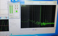
I assembled my first JlH amp, basically 1969 schematic with transformer regulated supply. 27v 1,3a.I used genuine 2sc5200 transistors and hopefully genuine 2sa970 and 2sc2240. Had to add some 10-15 pf on transistors and 22 pf on feedback resistor.
Attached some measurements of thd at 4-5w with cheap sound card and square valve at 20khz.
Does it look adequate? The sound is quite good and no audible noise.
Also, what is a recommendation for output capacitor? Brands, etc, will an expensive output cap make a noticeable difference in this application?
Attachments
Nigel, I I'm not sure how to interpret your reply and if it is addressed to me. As I mentioned, I have not much experience with SS amplifiers.
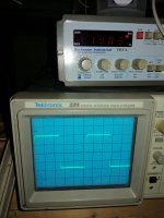
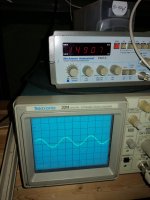
My signal generator could only do 1,5 MHz, so the attached picture shows the amp output sign wave at this frequency. Quite a good sign wave, but the signal is about a half tall.
My signal generator could only do 1,5 MHz, so the attached picture shows the amp output sign wave at this frequency. Quite a good sign wave, but the signal is about a half tall.
Attachments
- Home
- Amplifiers
- Solid State
- JLH 10 Watt class A amplifier