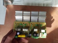
Today after work I finished one channel of my jlh, I have ordered the "correct" parts aka 2sa970 2sc3421 2sa1358, but I got impatient, and found a box with alot of bc560c and some bd139/140 suffix 16 and my old 2sc2608 2sa1117, soldered all together, and to my surprise it works much better than I could have imagined, no noise on jbl2405, almost zero offset and absolutely no oscillation ( checked with scope).
A happy story in a world of crisis.
A happy story in a world of crisis.
amplidude: Congrats! Did you try square wave in with a small cap parallel with the load too?
grunf: Do you have any possibility to make distortion measurements? Would be nice to see some distortion spectrum etc with your experiments!
At least for me it's easier to relate to measurements than a conclusion that it 'sounds good'. -Ok, the combination of a decent measurement and 'sounds good' is even better!")
From an engineering perspective it would be nice to see if and what the measured differences might be. I have measured a few different output transistors and versions of the JLH and for some reason, what measured slightly better than all others, sounded significantly better to me. (The modified ZeroZone PNP with Sanken 1216) I had other JLH's pretty close in distortion performance, but they never sounded as good. I posted some measurements earlier in the thread, but not so many seem to do that?
grunf: Do you have any possibility to make distortion measurements? Would be nice to see some distortion spectrum etc with your experiments!
At least for me it's easier to relate to measurements than a conclusion that it 'sounds good'. -Ok, the combination of a decent measurement and 'sounds good' is even better!
From an engineering perspective it would be nice to see if and what the measured differences might be. I have measured a few different output transistors and versions of the JLH and for some reason, what measured slightly better than all others, sounded significantly better to me. (The modified ZeroZone PNP with Sanken 1216) I had other JLH's pretty close in distortion performance, but they never sounded as good. I posted some measurements earlier in the thread, but not so many seem to do that?
Last edited:
No I didn't get that far, been listening to Boston instead, but I will to some more extensive testing tomorrow, I have Jan diddens auto ranger and arta, will post results tomorrow.
One thing I had to change was the 50r trimmer for bias, I used a 200r and was better able to trim.
One thing I had to change was the 50r trimmer for bias, I used a 200r and was better able to trim.
Sounds good! If I may make some wishes, would you do some 1k, multi-tone and two-tone FFT spectrum graphs in the normal power range (1W or so) with ARTA?
For your own interest, you can try different loads too, to see how well it copes with variations, and how Iq affects the distortion with load variations.
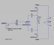
As a side note, I just installed this simple clipping and power indicator on my JLH. Nice to have some kind of clipping indicator on a low power amp like this. Ok, the amp can run out of current before it hits the rail, but it's simple, and better than nothing. I snatched the idea somewhere here on the forum, and just added the power LED since I missed that. Note that the diodes/LED's in the simulation are not the ones I actually used.
For your own interest, you can try different loads too, to see how well it copes with variations, and how Iq affects the distortion with load variations.
As a side note, I just installed this simple clipping and power indicator on my JLH. Nice to have some kind of clipping indicator on a low power amp like this. Ok, the amp can run out of current before it hits the rail, but it's simple, and better than nothing. I snatched the idea somewhere here on the forum, and just added the power LED since I missed that. Note that the diodes/LED's in the simulation are not the ones I actually used.
Attachments
Last edited:
Nice and practical circuit you have there, I might just copy it
Yes I will try your suggestions I only have a 8 ohm load unfortunately, but can try it with different capacitors, right now it's running on only two output transistors and from two bench supply, before measurements I will have to make a more stiff power supply
Yes I will try your suggestions I only have a 8 ohm load unfortunately, but can try it with different capacitors, right now it's running on only two output transistors and from two bench supply, before measurements I will have to make a more stiff power supply
Use it! I copied it myself, because I liked the simplicity, just like I like the simplicity of the JLH.
I think the bench supply and just about any load resistor will do for the low power testing. Maybe you have some 5W 8ohm resistors from some crossover or something to put in parallel with the load you already have? Then you can easily test up to 10W @ 4ohm.
I have actually not tested much at max power, since I don't find it so relevant. I just turn up the signal to see what happens, and usually spectrum gets really ugly when approaching clip levels. Playing 'full level', there are only brief peaks going that high, but most of the 'information' will be in the low power range, maybe 10dB down or more.
Hello again,
I'm not experienced in making measurements, you talked about different loads, I have it now hooked up to a 4.7 ohm resistor and a capacitor decade, which capacitor values are normally used in testing
I'm not sure what others use, maybe 0,1uF? I have a 0,5uF with leads that I've been using. I just hold it on by hand for a short while watching the scope to see if it goes crazy or not. As I understand it, this is just a stress test to see what happens, some oscillation is ok, but it should be damped. If the amp goes berserk, its not very stable.
Also take a look at square wave with normal 4 & 8ohm. There should not be any oscillation, some say overshoot is acceptable.
Why not test it with single and double outputs too? Iq can't be very high with single outputs of course..
I've been reading in this thread and seen yours and others post their measurements,, the capacitor box can do anything from few pf uptill 2uf.
I noted there that most measurements here a purely resitive.
I'll give it a go tommorow.
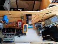
Regarding the pic yes I'm downunder, it's a mystery why my tablet always rotates my pics.
I noted there that most measurements here a purely resitive.
I'll give it a go tommorow.
Regarding the pic yes I'm downunder,
it's a mystery why my tablet always rotates my pics.Nigel
A simulation with your suggested circuit component list. Operated here at +/-12V with 8 ohm load. Distortion at 1W and 1kHz simulates at .035%.
Note that the components are rather different from the ones specified in previous post.Distortion will be higher if using 4 ohms and pots will need retuning.
Distortion with 8 ohms creeps up to 0.15% at 7W.
Actually this is one instance where the original hometaxial RCA 2N3055 works better because it had virtually zero quasi-saturation. That makes it a lot better at low voltages than any epi equivalent device I've seen - at 1kHz though. Beyond 10kHz it would struggle.
But I'm sure the simulator I'm using does not know about q-s anyway (I think it can be made to with a model/spec tweak) so is likely to be giving an optimistic distortion figure at higher powers.
I feel a bit guilty asking so much. Thank you John and an eye opener.
I put an earth choke on my NAD 3020. It sounds better ( 12 mH, mains side, be careful ). I suddenly realise I have no idea exactly why. There must be an impedance to somewhere that isn't live or neutral except by leakage. Sure I understand chokes. What I don't understand is the circuit to draw after the choke. It tightens and sweetens the sound. Fine it's a differential amp so should. I just don't see the anchoring points. Perhaps it is leakage. Ironic if so as it removesw earth at RF. RF loop ?
Okay got some readings.
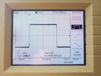
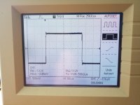
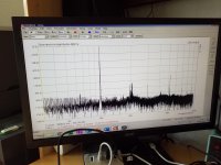
All measurements are taken with 20 volt supply rails and 1a bias, the load is 4.7 ohm.
Voltage across the resistor is kept at 1 volt rms.
Pic 1.
1 khz 4r7 load
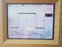
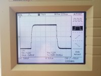
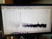
Pic 2.
1 khz 4r7 load and 0.5uf.
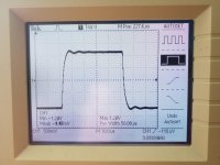
Pic 3.
1khz 4r7 load and 1uf.
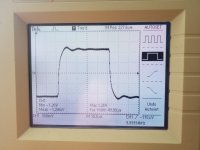
Pic 4.
10khz 4r7 load.
Pic 5.
10khz 4r7 load and 0.5uf.
Pic 6.
10khz 4r7 load and 1uf.
I can surely see the stress the capacitor causes.
Will measure some more
All measurements are taken with 20 volt supply rails and 1a bias, the load is 4.7 ohm.
Voltage across the resistor is kept at 1 volt rms.
Pic 1.
1 khz 4r7 load
Pic 2.
1 khz 4r7 load and 0.5uf.
Pic 3.
1khz 4r7 load and 1uf.
Pic 4.
10khz 4r7 load.
Pic 5.
10khz 4r7 load and 0.5uf.
Pic 6.
10khz 4r7 load and 1uf.
I can surely see the stress the capacitor causes.
Will measure some more
Attachments
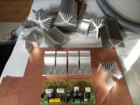
And here are two arta measurements, again at 1 amp bias and 1 volt rms across 4r7 resistor, 1khz and 10khz, I'm sure I can lower the noise floor more with better cable dressing and maybe crank the bias higher, but the outputs got alarming hot, still only using two outputs, and the insulators were some old I had laying around, I ordered some new ceramic insulators and to-3 sockets, do any of you have experience with the ceramic insulators??
I saw two different thicknesses 1mm and 2mm, I went for the thinnest, the thick are some ussr army leftovers, the dealer said they might be berylium oxide, I've heard it should be a great heat conductor.

Ps. Tried also same with 500nf, THD was unchanged.
I saw two different thicknesses 1mm and 2mm, I went for the thinnest, the thick are some ussr army leftovers, the dealer said they might be berylium oxide, I've heard it should be a great heat conductor.
Ps. Tried also same with 500nf, THD was unchanged.
Attachments
Last edited:
I would use 0.7A bias. Lets be honest. 5 watts 20 watts 100 watts. It's 5 to 100 that is a big difference. PSU colouration is reduced if lower bias. If the third harmonic drops and the rest is looking nice then best use 1 amp.
The big problem is an electrical insulator is also a heat insulator. As 400VDC could be used the insulator might be a poor heat conductor. It's the inability for electrons to move that is the factor. What one could do is use one NPN direct to the heat sink and two at the bottom on washers. Double high gain VAS if so.
The big problem is an electrical insulator is also a heat insulator. As 400VDC could be used the insulator might be a poor heat conductor. It's the inability for electrons to move that is the factor. What one could do is use one NPN direct to the heat sink and two at the bottom on washers. Double high gain VAS if so.
I would like a lower bias, I don't like those hot outputs, but whilst watching arta spectrum analyzer I could se THD getting lower with increased bias, but again the high currents do increase psu ripple drastically, so adjust it to lowest possible 3rd harmonics would be ideal, I hear you regarding insulators, and I'm a bit skeptic but will try them out, and why not get a before and after temp reading se it's any good, come to think I do have a large to-3 tunnel heatsink, with separate heatsink for each device, for direct mounting, vertical raised the chimney effect could do the trick, I'm not interested in forced cooling
Four smaller heatsink insulated from each other could be best. No insulators required. Some heat transfer compounds look like washers. Like me you probably use what you have. It's not the heatsinks as much as transistor temperature. You can find an amplifier that has worked hot suddenly fails.
- Home
- Amplifiers
- Solid State
- JLH 10 Watt class A amplifier