Nigel, I simulated with three BC337's in the driver stage with 3.3 ohm emitter resistors. Used a different gain device for each (-16,-25, -40) and for the 3055 variant the currents were within 1mA of each other (~7mA each) and dissipating 110mW. That seems to work.
Not sure if parallelling the input devices are needed for a PA input stage, where signal levels are pretty high. BUt for lower noise I'd suggest four that should reduce the noise by 2x. the devices ought to have emitter resistors too.
Not sure if parallelling the input devices are needed for a PA input stage, where signal levels are pretty high. BUt for lower noise I'd suggest four that should reduce the noise by 2x. the devices ought to have emitter resistors too.
Last edited:
You got there first. I wasn't thinking, it's not the usual VAS. Naim used 15R on phono stage. The 2k2 just trims things. I definitely will build this. I have some BC 337 and 327 on my shopping list. 100 of each. I have used them for many applications. Relay drivers on NE555 and protection crowbars to lm317. You crowbar the voltage divider down to 1.25V.
Hello all,
Came across this last night from Mr Jurgen Schmid
On Paul Kemble's page: http://www.angelfire.com/sd/paulkemble/sound3b.html
Perhaps for them as don't want 20 watts just 10 but with no output capacitor
Cheers
Came across this last night from Mr Jurgen Schmid
An externally hosted image should be here but it was not working when we last tested it.
On Paul Kemble's page: http://www.angelfire.com/sd/paulkemble/sound3b.html
Perhaps for them as don't want 20 watts just 10 but with no output capacitor
Cheers
I really like that. +'-12 V could be used. It would drive my bafles. I wonder if John could do sims with BC327 and 2 x BC337. The NAD 3020 has a mild similarity in not usinga differential input pair. TIP3055 could work at perhaps 2A. Could SMPS be added in series. Linear can. That only requires two bridge rectifiers and 2 x 7809 or 7812. Despite what people say they are reasonable. The doubt is signal 0V and SMPS not always liking Earth being like Neutral. Paul Kemble I slightly prefer to any other.
Isn't the JLH a gift at times might this. I have a hunch what we are doing now is the better JLH update since 1969. We need to to use devices we an get. K I S S. Keep it simple stupid as my brother taught me.
Isn't the JLH a gift at times might this. I have a hunch what we are doing now is the better JLH update since 1969. We need to to use devices we an get. K I S S. Keep it simple stupid as my brother taught me.
They could work indeed but if those semis are genuine NOS Sanken TO3 parts, they would be worth quite a bit of cash now. I think their best use would be in restored vintage class AB amplifiers, where their greater bandwidth and gain is a distinct advantage over standard power semis. However, I guess you want to keep them but haven't yet found a suitable project.
Otherwise, check that your amp doesn't become unstable with these and similar high performance audio power semis. Usually, if there is instability in simple class A amps, it can be corrected with just small capacitors shunting the feedback path but this still requires at least an oscilloscope and some familiarity with the problem to solve it properly.
Otherwise, check that your amp doesn't become unstable with these and similar high performance audio power semis. Usually, if there is instability in simple class A amps, it can be corrected with just small capacitors shunting the feedback path but this still requires at least an oscilloscope and some familiarity with the problem to solve it properly.
My favourite oscilloscope is a very modest 10 MHz single trace type. It is so reliable and is kept in less than ideal conditions. It never seems too low grade to work for amplifier testing. Sometimes it gives a better picture than my PC ones. Looking at eBay UK £50 bought a Fluke 100 MHz dual trace scope. I was tempted. I have a Gould scope much like that.
I'm not sure that that DC at the output will be all that stable with that simple approach to eliminating the capacitor. If you notice, as JLH continued to develop the design, he regulated both bias and offset DC settings of versions without capacitors. I dare say he noticed a bit of a problem there, probably not a serious one though........On Paul Kemble's page: http://www.angelfire.com/sd/paulkemble/sound3b.html
Perhaps for them as don't want 20 watts just 10 but with no output capacitor....
Thanks for answering.They could work indeed but if those semis are genuine NOS Sanken TO3 parts, they would be worth quite a bit of cash now. I think their best use would be in restored vintage class AB amplifiers, where their greater bandwidth and gain is a distinct advantage over standard power semis. However, I guess you want to keep them but haven't yet found a suitable project.
Otherwise, check that your amp doesn't become unstable with these and similar high performance audio power semis. Usually, if there is instability in simple class A amps, it can be corrected with just small capacitors shunting the feedback path but this still requires at least an oscilloscope and some familiarity with the problem to solve it properly.
They are indeed genuine there are 12 2sc2608 and their complementary 2sa1117, but they are used, pulled from an old 90s high end amp.
I will give them a try, and watch out for oscillation, and should it happen I know where to turn...
")
Greetings folks..!
I'm currently building the jlh2003 amp with pcb from fleebay, I have a fair amount of sanken 2sc2608 could they work as output transistor?
Thanks in advance.
Hello!
I have the same boards that I tried with fast transistors, and they oscillated. It seemed to be some trouble in the upper area of the driver/ccs. After I put in 15003's it was stable. I never had oscillation problems with the older JLH version with bootstrap cap on the upper transistor.
To be clear. The only reason to use higher speed transistors is they often are higher gain. What you will be listiening to is the transistor being more gentle with the driver stage which to be honest isn't quite good enough. At JLH current PNP could be higher gain. TIP2955 looks ideal if the curves I see are reliable.
JLH has very little to teach an amplifier like Rotel RA931 class AB. That uses very fast common transistors to hide the crossover distortion. Regardless of how fast it is faster would be better if stability maintained.
Douglas Self points out that some sustained beta transistors do have lower open loop distortion. However a complimentary feedback pair can be many times lower even using transistors like BD139/140:TIP2955/3055. I have a hunch a well designed JLH using BC337 input 2 x BC327 VAS and 2 x TIP2956 outputs in a blind test could be the definitive type.
Significantly more than 8 watts is 100 watts. The Quad 405 never sounded a real 100 watts and if sustained isn't. If an amplifier of 8 watts isn't loud enough it's the loudspeaker. I did up a Siemens cinema amplifier. 1.3 watts 0.1% THD. 13 watts 1.3% THD. 100 watts 10% THD. The 1.3 watts being enough to offer typical listening for 300 plus audiences. This was a 1950s design. The 100 watts in class AB and below in class A. 10% THD for 007 explosions would be fine. I thought the sound was interesting. The longtail pair EF41 pentodes on a fantastic choke power supply. The twin EL34 at 820V ( yikes ) on raw DC. Modern EL34 glow blue due to not being good enough. My very simple A plus AB amplifier was inspired by this.
It sounds like I'm heading for troubles,
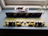
I'm also planning to use the to3 alu angle shown in picture, cut of course to support 4 to3,
That means short cabling which also invites oscillation, but my build is low budget so I only bought a970, well it has to be tested in real life, maybe I'm lucky.
Another question i have is, how important is the 0r1 resistors value ? I currently installed 0r18, again because i had them, if it's no good i have lots of noble 0r22 5w cement, two in parallel.
And again, thanks guys, it's great to have support of some genuinely knowledgeable guys.
Nigel
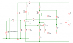
A simulation with your suggested circuit component list. Operated here at +/-12V with 8 ohm load. Distortion at 1W and 1kHz simulates at .035%.
Note that the components are rather different from the ones specified in previous post.Distortion will be higher if using 4 ohms and pots will need retuning.
Distortion with 8 ohms creeps up to 0.15% at 7W.
Actually this is one instance where the original hometaxial RCA 2N3055 works better because it had virtually zero quasi-saturation. That makes it a lot better at low voltages than any epi equivalent device I've seen - at 1kHz though. Beyond 10kHz it would struggle.
But I'm sure the simulator I'm using does not know about q-s anyway (I think it can be made to with a model/spec tweak) so is likely to be giving an optimistic distortion figure at higher powers.
Attachments
I would like to add that linearity (hfe/current) also seems to be a factor when it comes to output transistors.
+1 for this.
There was a chap here downunder (Peter Ellis? of ME Amps) who dealt with the problem of speaker interaction by decoupling his VA from the current amp (output stage). In the chatter that surrounded these amps, those in the know claimed that , as well as matching devices (as he couldn't rely on global NFB) selection for B linearity (and biasing to the most linear part) played a role in getting these "impossible to manufacture" amps to work.
Schematics, as far as I know, have never been published so there's a little bit of "woo" around the amps. But they hold their value, if and when they come up for resale.
thoglette -quite right to point out the use of transistors with better gain-current characteristics (flat rather than linear - which could still imply a gradient! - perhaps) in the JLH amplifier.
Unfortunately the quasi-saturation most modern devices also exhibit means running the amps at a higher voltage, and higher dissipation, than we would really like. If low distortion at max. power is important. Because q-s changes the gain flatness at low voltages significantly.
Unfortunately the quasi-saturation most modern devices also exhibit means running the amps at a higher voltage, and higher dissipation, than we would really like. If low distortion at max. power is important. Because q-s changes the gain flatness at low voltages significantly.
Doesn't anyone read my posts, I've written at least five times that the JLH69 can work with high speed transistors and CCSs.
I tested over 40 types of various transistors for the Tr3, some were 400-500MHz and worked in an amplifier without any oscillations, the outputs I now use are 85MHz at 2A and again no oscillations.
For Tr3, the problem is not high fT, but low Cob. The output transistors have an hFE of 190, and the Tr3 has an hFE of 400 so that's not a problem either.
The problem seems to be fake transistors and poorly designed circuit boards and power supplies.
grunf- I've also said (a few times) that fast transistors can work. I've got a 10W using 2SC5200 which did not need any compensation. With MJL3281A's it needed a 33pF cap across the feedback resistor.
I agree, at HF lead lengths are important, if not critical. If longer than about 100mm small decoupling capacitor(s) should be wired across the transistor electrodes (depending on whether using SE or DC coupled) from collector to gnd.
I agree, at HF lead lengths are important, if not critical. If longer than about 100mm small decoupling capacitor(s) should be wired across the transistor electrodes (depending on whether using SE or DC coupled) from collector to gnd.
grunf- I've also said (a few times) that fast transistors can work. I've got a 10W using 2SC5200 which did not need any compensation. With MJL3281A's it needed a 33pF cap across the feedback resistor.
I agree, at HF lead lengths are important, if not critical. If longer than about 100mm small decoupling capacitor(s) should be wired across the transistor electrodes (depending on whether using SE or DC coupled) from collector to gnd.
I got almost 25W from the 2SC5200 without any oscillations and compensation with a fast Tr3.
I only need compensation if I put NEC's 2SC1941 for Tr3, 4.7pF was enough.
Now for the input transistor I am currently using 2SA1312, Tr is 2SC1941 and output 2SC3284, the compensation is 4.7pF.
This combination of transistors sounds best to me. 2SC5200 cannot be compared to 2SC3284 in this case.
Instead of 2SC1941 I can put 2SC2682 and then I don't need those 4.7pF and the sound will be almost the same.
2SC1941 used Rotel as a VAS transistor in its amplifiers.
Last edited:
- Home
- Amplifiers
- Solid State
- JLH 10 Watt class A amplifier