x-pro said:"Single-BJT splitter" in JLH circuit is very symmetrical, as it splits the current, not the voltage.
x-pro
I thought the driver in the JLH split the phase: so the phase on the collector is 180 degrees opposite of the phase on the emitter. That way, the output stage works in push-pull.
Hi Millwood,
Becarefull with simulation! You need to take the good set of conditions like:
1 watt in 8 Ohm
or
9 Watt in * ohm
Saying full power means nothing as this can be difined as power at 10% THD or power at 1%THD..
I think is save to use allways to measure:
- at medium power/average listening power ( eg. 1 Watt) and
-at highest power before the onset of clipping/saturation of the transistors .. for 30Volt MOSFET version this is about 8.8 watts
The bootstrap really decreases the THD so I tyhink you did something wrong..
Their really is no need to put 40mA through a driver BJT if it's AC current is some hunderds uA.. just use about 8 mA and scale the resistor accordingly...
I think I know now why the BJT/MOSFET replacement work, be not shure yet.. cya tommorrow?
Greeting and goodnight
Thijs
I thought the driver in the JLH split the phase: so the phase on the collector is 180 degrees opposite of the phase on the emitter. That way, the output stage works in push-pull.
It does split the phase.. the AC current are in opposite phase. That way the output stage works in push-pull. It is current driven .. not voltage driven.. allthough this assumes exact equal Hfe.. there's a snag to it, but let's not make things more complicated than strickly neccesary.
gr,
T
Hi Millwood,
Looking at your graphs, I can only assume something must have gone wrong.. these graphs look awwful and do not remotely look like my results. Can you post the circuit you actually used, maybe there's a small mistake somewhere? Furthermore the Idle current is way too high.. let use 1.5 A for a 30 Volt MOSFET version.
PS
The driver has 4 mA Iq in my version not 8mA as posted earlier
tschrama said:Can you post the circuit you actually used, maybe there's a small mistake somewhere?
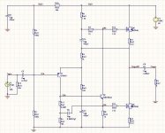
here it is. It is essentially my version using higher resistor values for the driver stage.
I have the bootstrap turned off in this particular simulation and it can be turned back on easily. however, it is not going to materially change the picture. The simulator is protel dxp (demo).
tschrama said:PS
The driver has 4 mA Iq in my version not 8mA as posted earlier
yeah. That's essentially the Vds over that 1k resistor on the emitter of the driver.
Attachments
tschrama said:Becarefull with simulation! You need to take the good set of conditions like:
1 watt in 8 Ohm
or
9 Watt in * ohm
Saying full power means nothing as this can be difined as power at 10% THD or power at 1%THD.. Thijs
what I did is to inject 1v peak (0.7v rms) 20khz signal into the input and measure the output. I have no way to control on the output / speaker easily.
tschrama said:Hi Millwood,
Looking at your graphs, I can only assume something must have gone wrong..
one way to assure yourself that the graph is correct is to do a RE1(i) - RE2(i) graph: it is almost a perfect sine wave. If you use Kirchoff's law on the node (where feedback is taken), that (RE1(i)-RE2(i)) is exactly the output current on the load resistor.
tschrama said:It does split the phase.. the AC current are in opposite phase. That way the output stage works in push-pull. T
the push-pull thing isn't just due to the current in opposite phase: voltage in opposite will do the trick as well. I think this current-driven or voltage driven talk is futile as it leads us nowhere and doesn't enhance our understanding of the situation.
I don't know what you guys meant by "spliting current" or "upper current exactly matches lower current". there is no mechanism that I can see that ensures the base currents are exactly the same for the upper and lower output devices. Furthermore, the upper output current cannot be exactly the same as the lower output current: if that's true, there will be no output current.
so I don't know what you guys are talking about. maybe you or x-pro can shade some light on this.
I haven't traced through the PCB pattern, but I really suggest you should build a prototype of the circuit before committing to a PCB unless you have a cheap way of making PCBs. Even if you were to just build up one side and run it into an appropriate dummy load, you will still probably learn something that will change your PCB a bit.Devil_H@ck said:I'm sorry to kind of bump this thread, but it seems that due to my post showing up later (since I'm new), nobody has noticed it.
Could you guys please take a look? Here is the post: http://www.diyaudio.com/forums/showthread.php?postid=282346#post282346
Thanks!
These MOSFET JLH posts really deserve to be separated out, I wonder if a kind-hearted Moderator would consider moving them to their own thread.
Hi Millwood,
I use 400mV peak input to give about 1 Watt in 8 ohm. Lets stick to that to ensure enough freedom from saturation/clipping effects.
You circuit looks OK to me ... so what happend... maybe it is your simulation: I use 1Khz.. escpecially with a MOSFET output stage this can be of significance.. I 'll try 20KHz, could you try 1KHz?
Yes is does.. keep trying.. read the original article, draw again and again and don't stop thinking about it..
The original BJT circuit works in the current domain:
-the upper BTJ get an current injected to it's base, this determines the current through it's emmitor.
-When the driver BJT 'steals' a bit of that current, the up BJT will put less current through its emmittor.
- The current that the drivers 'steals' goes through it's collecetr, to its emmitor.. injecting more current in the base of the lower BJT.. icreasing its current draw.
So the output BTJ are current driven, they are driven by a phase splitter that 're-distributes' the base-currents of the output BJT.
X-pro.. this is about right isn't? help me out because I lack the talent to explain things more cleary...
So just replacing the output BJTs with MOSFET might not work. But is does! Why? I think I know now...
In my simulations the lower driver transitor is 1K... The an AC voltage across this resistor is vreated by and AC current through the driver BTJ.. this current has no where to come from except from the upper 1.5K and 1K resistor pair.. The Vgate of the upper MOSFET is changed by the bootstrap capacitor: in effect following the output AND by the current going through the UPPER 1K resistor.. so Vgs is changed simmilar as the lower MOSFET: nice ac-current sharing
Hope this helped..
conclusion:
1]Keep the lower-driver-resistor equal to the upper-driver-resistor and current-sharing is achieved..
2] use the most upper driver-resistor (1.5K in my sims) only to adjust Iq
I just did a 20KHz sims.. I get the same results as you nasty!! must be because of the MOSFETs gate capacitance .. I see the same 300uAp... 600uApp!
The bootstraphoqwever does improve thing by 10dB in my sims.
regards,
Thijs
I use 400mV peak input to give about 1 Watt in 8 ohm. Lets stick to that to ensure enough freedom from saturation/clipping effects.
You circuit looks OK to me ...
so what happend... maybe it is your simulation: I use 1Khz.. escpecially with a MOSFET output stage this can be of significance.. I 'll try 20KHz, could you try 1KHz?the push-pull thing isn't just due to the current in opposite phase: voltage in opposite will do the trick as well. I think this current-driven or voltage driven talk is futile as it leads us nowhere and doesn't enhance our understanding of the situation.
Yes is does.. keep trying.. read the original article, draw again and again and don't stop thinking about it..
The original BJT circuit works in the current domain:
-the upper BTJ get an current injected to it's base, this determines the current through it's emmitor.
-When the driver BJT 'steals' a bit of that current, the up BJT will put less current through its emmittor.
- The current that the drivers 'steals' goes through it's collecetr, to its emmitor.. injecting more current in the base of the lower BJT.. icreasing its current draw.
So the output BTJ are current driven, they are driven by a phase splitter that 're-distributes' the base-currents of the output BJT.
X-pro.. this is about right isn't? help me out because I lack the talent to explain things more cleary...
So just replacing the output BJTs with MOSFET might not work. But is does! Why? I think I know now...
In my simulations the lower driver transitor is 1K... The an AC voltage across this resistor is vreated by and AC current through the driver BTJ.. this current has no where to come from except from the upper 1.5K and 1K resistor pair.. The Vgate of the upper MOSFET is changed by the bootstrap capacitor: in effect following the output AND by the current going through the UPPER 1K resistor.. so Vgs is changed simmilar as the lower MOSFET: nice ac-current sharing
Hope this helped..
conclusion:
1]Keep the lower-driver-resistor equal to the upper-driver-resistor and current-sharing is achieved..
2] use the most upper driver-resistor (1.5K in my sims) only to adjust Iq
I just did a 20KHz sims.. I get the same results as you
nasty!! must be because of the MOSFETs gate capacitance .. I see the same 300uAp... 600uApp!The bootstraphoqwever does improve thing by 10dB in my sims.
regards,
Thijs
tschrama said:-the upper BTJ get an current injected to it's base, this determines the current through it's emmitor.
-When the driver BJT 'steals' a bit of that current, the up BJT will put less current through its emmittor.
- The current that the drivers 'steals' goes through it's collecetr, to its emmitor.. injecting more current in the base of the lower BJT.. icreasing its current draw.
that makes sense. It also suggests that if you replace the collector bootstrap and emitter resistor on the driver with two perfect current source, you will improve performance. Has anyone tried that?
tschrama said:So the output BTJ are current driven,
I can make a similar argument in voltage as well: As the voltage ont he base of the driver goes up, it raises the voltage on and current through the emitter resistor, such turning on the lower output BJT more. As the emitter current goes up, voltage drop off the collector bootstrap goes up (think of it as a resistor for now). that means Vbe for the upper BJT goes down, turning OFF the upper BJT. Viola, you got a push-pull design.
The same holds true for the mosfet version as well, except that you will be talking about Vgs.
tschrama said:I just did a 20KHz sims.. I get the same results as you
Thijs
I have learnt from simulating various mosfets that you always simulate at high frequency,
Hi Millwood,
Pfffff .. thats a bit muck for a simple mind as my to follow, but I'll work on it... thanks.
Yes.. I think it might.
Your also right about the drivers current and high frequency aspects of your circuit... keeping the associated resistors of the drivers low is the only way to deal with the MOSFETS gate capacitance.. this dictates high current through the driver.. I should have done some 20KHz sims earlier...
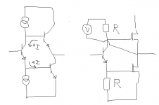
I made a correct version of the simplfified topology that help me tto visualize things...
Kind regards,
Thijs
I can make a similar argument in voltage as well: As the voltage ont he base of the driver goes up, it raises the voltage on and current through the emitter resistor, such turning on the lower output BJT more. As the emitter current goes up, voltage drop off the collector bootstrap goes up (think of it as a resistor for now). that means Vbe for the upper BJT goes down, turning OFF the upper BJT. Viola, you got a push-pull design.
Pfffff .. thats a bit muck for a simple mind as my to follow, but I'll work on it... thanks.
that makes sense. It also suggests that if you replace the collector bootstrap and emitter resistor on the driver with two perfect current source, you will improve performance. Has anyone tried that?
Yes.. I think it might.
Your also right about the drivers current and high frequency aspects of your circuit... keeping the associated resistors of the drivers low is the only way to deal with the MOSFETS gate capacitance.. this dictates high current through the driver.. I should have done some 20KHz sims earlier...
I made a correct version of the simplfified topology that help me tto visualize things...
Kind regards,
Thijs
Attachments
Hi Millwood,
my sims tell me that for optimum current sharing between the MOSFETS you need the make the upper-driver-resistor 0.85 * value of the lower-driver-resistor
In my circuit this means 850 Ohm upper, 1000Ohm lower..
I see in you circuit upper 220 Ohm, lower 110 ohm ... I think you amplifier is allmost a SE-amplifier.. scaling these resistor properly might improve thing a lot...
goodluck,
Thijs
PS
I designed a total MOSFET version of the amp a bot 1 or 2 years ago.. maybe in this very thread... using IRF610 as input and drivers... simulated great!
http://www.diyaudio.com/forums/showthread.php?s=&threadid=2274&highlight=
I've learned a lot in the mean time .. so don't take this design serious...
my sims tell me that for optimum current sharing between the MOSFETS you need the make the upper-driver-resistor 0.85 * value of the lower-driver-resistor
In my circuit this means 850 Ohm upper, 1000Ohm lower..
I see in you circuit upper 220 Ohm, lower 110 ohm ... I think you amplifier is allmost a SE-amplifier.. scaling these resistor properly might improve thing a lot...
goodluck,
Thijs
PS
I designed a total MOSFET version of the amp a bot 1 or 2 years ago.. maybe in this very thread... using IRF610 as input and drivers... simulated great!
http://www.diyaudio.com/forums/showthread.php?s=&threadid=2274&highlight=
I've learned a lot in the mean time
.. so don't take this design serious...millwood said:that makes sense. It also suggests that if you replace the collector bootstrap and emitter resistor on the driver with two perfect current source, you will improve performance. Has anyone tried that?
I tried it on the original jlh bjt. the lower bjt is working but not the upper bjt: it was either turned full on or full off. I used two perfect current source of 40ma each. I need to figure out why.
I was referring to the JLH power supply that Devil_H@ck posted. You guys are way above me as far as simulations go. Have fun.tschrama said:Hi Paulb... I agree... could you gives us a helping hand with the analysis of the circuit?
Kind regards,
Thijs
tschrama said:my sims tell me that for optimum current sharing between the MOSFETS you need the make the upper-driver-resistor 0.85 * value of the lower-driver-resistor
I will try that later.
tschrama said:I designed a total MOSFET version of the amp a bot 1 or 2 years ago.. maybe in this very thread... using IRF610 as input and drivers... simulated great!
http://www.diyaudio.com/forums/showthread.php?s=&threadid=2274&highlight=
I've learned a lot in the mean time
our designs are surprisingly similar, putting aside that we used different input and driver transistors.
Hi Millwood...
This was fun, thanks for all the discussion.. I really would like to know what happend if your adjust the driver resistors...
I was thinking.. maybe you could feed you amp with a test signal.. like a sine wave.. and measure the AC-voltage across both MOSFET output resistors.. this way you could adjust the driver resistors for perfect current sharing...
I really wanna get me some of those IRF540s.. to try myself.. and I loveeeeeee your heatsink!!!
Keep us posted!!
Regards,
thijs
tschrama said:I was thinking.. maybe you could feed you amp with a test signal.. like a sine wave.. and measure the AC-voltage across both MOSFET output resistors.. this way you could adjust the driver resistors for perfect current sharing...
I will try that.
tschrama said:I really wanna get me some of those IRF540s.. to try myself.
it doesn't have to be the 540s. Other mosfets I am sure work just as well.
tschrama said:I loveeeeeee your heatsink!!!
yeah, I know. you got do with whatever you have,
Once I have experimented enough with the existing amp, I will build a new one. I made quite a few layout errors with the existing board.
- Home
- Amplifiers
- Solid State
- JLH 10 Watt class A amplifier