Hee?? why did that thread die.. looks very interesting! Thanks for the link..
http://www.diyaudio.com/forums/showthread.php?s=&threadid=14320
http://www.diyaudio.com/forums/showthread.php?s=&threadid=14320
tschrama said:Mean while I have drawn the 'JLH 10W Class A Triangle output stage' (lets call it triangle in short) in simplified form to analyze.. one version fo BJT (assume equal Hfe) , and one for MOSFET (assume equal transductance)
I'll attache a drawring... maybe it helps ... maybe not..
First circuit works, second - doesn't . With mosfets a very small current change in the driver will produce a lot of voltage on the top and just a little bit at the bottom, so the bottom MOSFET is a current source. I've started to think about this problem 11 years ago
and came up with that circuit I've posted earlier. Now add a resistor with the same value R between the gate and source of the top MOSFET . Suddenly it works beautifully. Not very obvious, thought . I did not believe it would work properly till I've assembled one I've posted. Now it is clear to me how it works, but back than it was very unusual - I've never seen anything like it.x-pro
Hi,
exactly! That was what I thought... The MOSFET version won't work. But that is what Millwood has done.. and it works ??? It simulates also very good... why do the two MOSFETs share current so neatly equal??
First circuit works, second - doesn't . With mosfets a very small current change in the driver will produce a lot of voltage on the top and just a little bit at the bottom, so the bottom MOSFET is a current source.
exactly! That was what I thought... The MOSFET version won't work. But that is what Millwood has done.. and it works ??? It simulates also very good... why do the two MOSFETs share current so neatly equal??
tschrama said:why do the two MOSFETs share current so neatly equal??
I am not sure if they do, either in the mosfet version or the in the orginal jlh version. For sure, the ac current going through them isn't the same (other than, there wouldn't be anything for the speaker,
).the idle current, or more precisely the DC voltage on the capacitor, is defined by the resistors R5, R13 and R14 in your circuit.
For example, assume that the Vgs for the mosfet is 4v (about the right number for the irfs). so Ir5=4ma. that caused about 10v drop over R13/R14. so the source terminal of the upper mosfet must be at 30-10-4=16v.
In my case, mine idles at about 18-19v.
Going back to x-pro's comment, I don't know if I would call the jlh BJT version symmetrical because you can never get a single-BJT based phase splitter symmetrical: it has zero voltage gain on the emitter resistor for the lower output device and it has considerable gain on the collector resistor for the upper output device.
I am not picky on if a device is voltage or current driven. To me, they are all variable resistors controlled by a signal.
I will try to simulate the double-barreled JLH (with a bootstrap on the input transistor) when I get time but it looked very interesting.
tschrama said:Hi, exactly! That was what I thought... The MOSFET version won't work. But that is what Millwood has done.. and it works ??? It simulates also very good... why do the two MOSFETs share current so neatly equal??
They don't. The top one just a follower loaded by a bottom one working as a current source. On DC their currents are the same (obviously
). But almost all AC current goes through only the top MOSFET. That is why this is Single-Ended circuit. Only ONE device amplifies. Second just creates the load (almost). The circuit would work, however it will be considerably less efficient than a Push-Pull class A amplifier. In the original JLH circuit whenever some signal current added to the base current of one device, the same amount is subtracted from the second device. This way BOTH transistors share AC current equally, thought in opposite phases. So JLH is a proper Push-Pull amplifier. x-pro
This is getting interesting I will try to write what I think.. (please excusse my poor english, I wish I could write better, my 'tone' might be a little off)
am not sure if they do, either in the mosfet version or the in the orginal jlh version. For sure, the ac current going through them isn't the same (other than, there wouldn't be anything for the speaker
In the BJT version they do (assume equal Hfe) ! And more importantly: the ac current going through them should be the same.. this give good Push-Pull working.. good efficietcy and good opne-loop linearity.. Note that the currents are in anti-phase.. the diffenrece is flowing to the speaker...
I don't know if I would call the jlh BJT version symmetrical because you can never get a single-BJT based phase splitter symmetrical: it has zero voltage gain on the emitter resistor for the lower output device and it has considerable gain on the collector resistor for the upper output device.
I think it is symmetrical. Maybe you are still thinking in voltage and not in current.. The BJT version is a very good current-splitter.. the voltage gain is than derived from the speaker inpedance and the Hfe of the driver/output trasistors.
I am not picky on if a device is voltage or current driven. To me, they are all variable resistors controlled by a signal.
In this topology it is important wheater a device it voltage driven (high input impedance) or current driven (low input impedance).
But I still don't understand why the MOSFET share current so neatly as they do in my sim? Furthermore I do understand that R5/R13/R14 set the Iq but preciely how the interact I do follow.. back to the sim...
Looking forward to your reply!!,
Greetings,
thijs
millwood said:
Going back to x-pro's comment, I don't know if I would call the jlh BJT version symmetrical because you can never get a single-BJT based phase splitter symmetrical: it has zero voltage gain on the emitter resistor for the lower output device and it has considerable gain on the collector resistor for the upper output device.
I am not picky on if a device is voltage or current driven. To me, they are all variable resistors controlled by a signal.
It is not a matter of your fancy
- BJT's are controlled by current and MOSFET's - by voltage. It makes a lot of difference for both circuit topology and it's analysis. "Single-BJT splitter" in JLH circuit is very symmetrical, as it splits the current, not the voltage. And it is current controls output BJT's. And the output, assuming equal hfe for both output devices, is controlled symmetrically. The voltage amplification here of a secondary importance. For MOSFET's the gate-source voltage is everything. It requires a different approach and topology. In my circuit two output MOSFET's get same input voltages on DC, providing the idle current, and same in amplitude but opposite in phase AC signals, controlling the AC current through the load in a proper push-pull fashion.
x-pro
P.S.
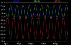
- tschrama is quicker than mehere is the current plot:
the blue line is the current from the top output device, and green fromt he bottom, and the red is what goes through the load. R1/R2 are 220ohm, rail is 36v. Standard schematic from the original JLH.
so unless you very carefully adjust R1/R2, the two transistors will NOT work equally in terms of their current output.
Attachments
tschrama said:I've just double checked:
The MOSFETs are sharing current equally in MillWoods version.. well equal..
488mA AC (lower) / 582mA AC (upper) .
my posted circuit, 1.2Vp in 9W out in 8 Ohm..
161mA / 196mA for 1W output
that's still close... . is it coincidence ?
gr,
Thijs
sounds like you are talking about idle current. the two will be very close. Otherwise, the DC voltage on the output capacitor will adjust automatically,
sounds like you are talking about idle current. the two will be very close. Otherwise, the DC voltage on the output capacitor will adjust automatically,
No, come on Millwood
. .. .. offcourse DC current must be equal oprecisely.. there's no other path for the current to go, but AC current can differe a bit.. DC current was set to 1.5xx A. The AC currents are as posted...
gr,
T
I just made a MOSFET version according to x-pro design.. and gues what..:
In class A (1.46 A Iq) the current are shared very, very, very simmilar to Millwoods MOSFET design.. scaringly so! 484mA lower, 586mA upper (about 9 watt out)
In class B (Iq 16mA, easely adjustble with the upper CCS of x-pro design) the current are shared far beter 572mA lower, 588mA upper ... (about 9 watt out)
I am afraid that there are very interesting things going on here that we haven't understood yet..
But 12 very nice features of the MOSFET design appear:
1] A extra bootstrap can be added, improving openloop gain and hence THD etc..
2] very easely adstable from Class A to Class B (with only slightly worse THD figures about -79dB versus -86dB at 9 watt out)
this if FUN
tschrama said:The AC currents are as posted...
gr,
T
I guess I am confused a little. The "current" going through the MOSFETS / BJTs has both DC and AC component. So when you quote just one figure for the "current", I am not sure if you meant the DC component, or the AC RMS value.
tschrama said:OK here it goes....
1]
The base inpedance of the second transistor is indeed low .. offcourse dependend on the Hfe, but around 8K Ohm.. and since this is parrallel with the 10K collector resistor of first transistor, open loop gain must really suffer...but since the lower MOSFET gate is a high impedance node (not like the 2N3055 version) things can be improved... using a 1K resistor to the gate of the lower MOSFET improves things a bit.. from 8 K to 52 K
Hi, tschrama:
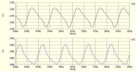
I simulated your design, and it works, to certain extend. The THD is just slightly higher, at 0.11% full power at 20khz.
the problem is I think with current going through the two output devices: they are nowhere near sine wave. I posted it here.
I think if you don't want to run at low Iq for the driver, this is the route to take, as there is a minimal penalty on sound quality.
Attachments
tschrama said:3]
lowering the 0.47 R resistor to 0.22 gives a somewhat higher openloop gain.. the voltage drive for the lower MOSFET is allmost halved...
5]allthough this is tricky.. loweriung the gate resistor from 220 to 100 Ohm help abit against too must openloop phase shifts and improves closeloop phase margin..
Regards,
Thijs
tschrama: you are right on both accounts: I had used 110ohm gate stoppers and 0.2ohm resistors on the real amp.
Good catch.
- Home
- Amplifiers
- Solid State
- JLH 10 Watt class A amplifier