High current also. In my work we use 600 amps transient using 50A bridge and is a 600V type. The cost is £1.
It also is a good low current idea as you say. It's temperature sensetivity can be a problem, worse than a lamp, better than RA53. Red LED's cost about 3 pence so not much more than 2 x 1N4148 or more if required. 1N4007 is also a good choice as it will do many things.
It also is a good low current idea as you say. It's temperature sensetivity can be a problem, worse than a lamp, better than RA53. Red LED's cost about 3 pence so not much more than 2 x 1N4148 or more if required. 1N4007 is also a good choice as it will do many things.
Two small 1.5mm square-base LEDs are about the most economical clamp for tru-hole mount space/price-wise. Less parasitics too. A small DIP bridge is same size as a 6-pin optocoupler, so not quite as efficient space/price-wise. A small mini-dip smd is the better option with surface mount imho.
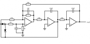
There is imho some space for improvement in your schem from post #4691: There is a direct injection of unwanted ultrasonic harmonics directly from IC1A thru "HP" link into output. These could be most likely filtered directly at IC1A with a small cap in parallel to 100K R3 (a 33pF? not sure how this would f*** up the phase relationships) and also across the diodes; to attenuate above H3. (The signal at IC1A '+' input is already filtered by IC1B so no need to do anything)... If doable, this would make filtering the summed output much easier.
But then - if the inverting topology makes so much better results - the output buffer could be made inverting as well; with 6K2/56K pair replacing the 3K/27K; and adding a 5K6 nfb resistor. Here too a cap could be added parallel to the nfb resistor to further clean-up...
Or merging this idea into a MFB topology.
If I get a moment I will try to build something like that. The problem there is the complexity gets greater than what I want. If you like the Elektor design will get a Sputnik up in space.
My big problem is I need to find better measuring equipment. A friend has an Audio Pression measuring station in Slovakia. I might post him the Elektor to measure.
One thing I can say. If the Elektor is genuinely as good as it is said to be I can infer the distortion of the JLH. As long as it is below my -75dB limit it most likely is true. Many measurements I make at -66db are correct by maths alone. If I get -70dB via JLH using the Elektor it most likely is -70dB.
Here are the facts. If the sine wave is the simple oscillation of RC then it can be the distortion of the op amp we measure. The Elektor lamp injects -66dB 3rd harmonic. As the feedback path from op amp B is important it must suggest why distortion is already below - 75dB at the output of op amp A. This should be impossible. What must be happening is a 3rd harmonic cancellation due to gain ratios and phase shift. A State Variable Filter Oscillator has enough gain to be more than a filter. The lamp even more so than in the HP patents ( 1938? ) is controlling the gain. Or rather it isn't. He says it controls the phase shift. If you take my example the R6 can be 18K, 27K or 36K with an adjustment to R6. If 18K lamp = 250 mVrms and 36K 440 mVrms. The output remains 2.2Vrms, one will be best if only I could measure it. Usually the range of a Wien is far less and is related to output in a 1:2 ratio.
This is where I might start for building a measuring tool.
http://www.vitalstates.org/diy/amplifiers/simple-thd-measurement.pdf
Opamp A is a diff-amp that also performs a summing action at the '-' input. Which means there is some "math" happening with the 3 signals that enter this stage.
My experience with diff-amps suggests that there could be some filtering performed within the same diff-amp stage, which could in some scenarios make a huge performance advantage. That's why I suggested to look into that (one single cap here could - or could not - make a difference).
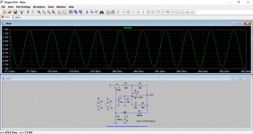
But I haven't ran any sim of this particular oscillator so far, so take that as a mere "possibility". (Read: I don't know what I'm talking about") ) I had a hunch though ...
) I had a hunch though ...
My experience with diff-amps suggests that there could be some filtering performed within the same diff-amp stage, which could in some scenarios make a huge performance advantage. That's why I suggested to look into that (one single cap here could - or could not - make a difference).
But I haven't ran any sim of this particular oscillator so far, so take that as a mere "possibility". (Read: I don't know what I'm talking about
) I had a hunch though ...It's hard to sim the Elektor as the lamp is a non linear load. The reason for that is the lamp is hotter at it's peak than when near 0V. The good news is the lamp has thermal lag so it won't cool down too much in the time of a 10 kHz wave. That's why it has 3rd harmonic distortion. That's good luck as 3rd harmonic is a few dB's down a filter curve 2nd isn't.
What Mr Elector says is the op amp C can have a resistor capacitor output ( 1K6 10nF 10 kHz ? ). If so at Fo the output will be -3dB down. If you have 2.2Vrms that is a still a reasonable 1.5Vrms you have for use. It should take the Elektor down from - 108db to - 117 db the Rosen standard. That is as long as the input impedance of the test device isn't low ( not like my poor example of the RA53 ). Not bad for £3 and a tabacco tin.
What Mr Elector says is the op amp C can have a resistor capacitor output ( 1K6 10nF 10 kHz ? ). If so at Fo the output will be -3dB down. If you have 2.2Vrms that is a still a reasonable 1.5Vrms you have for use. It should take the Elektor down from - 108db to - 117 db the Rosen standard. That is as long as the input impedance of the test device isn't low ( not like my poor example of the RA53 ). Not bad for £3 and a tabacco tin.
I really must borrow a good measuring device. I doubt anything below £100 will do. Please prove me wrong.
The beauty of the Elektor design is it should work for anyone new to electronics. It also is one step better than a JLH kit. That is instead of a cake in a box we buy flour, eggs, butter etc and make French four of everything cake. The trick with that is a knife inserted should come out sticky. If so it is cooked. That's the -108dB. That cake is exotic when the doing of it isn't. Omlette even more so. I can just about do French if it's food or wine ( Spanish almost ). Add apples to is to make it even more special.
Recette - Quatre Quarts traditionnel | 750g
An idea. (twin leds)
When I get a moment. I would guess it to give about -60 dB. It could be better. The actual limiter is about -12dB @ F3 at a guess. It would be about -9.5 dB if a squarewave limiter. It certainly would be interesting. Next Tuesday is my best chance.
Actually not. A mistake on the diag. is that 1k resistors should be 10k. The "filtering action" around the diffamp is a bit nervous and must be tuned to the osc. freq.
The diode-stabilized circuit as on ESP site would have a better behavior if tweaked around the diffamp. Especially the diode clamp would be imho better if the I/V knee would soften; there are simple ways to do that, fe. with a series resistor. A small SMD bridge would be beneficial as well. Best would be B-E transistor junctions; but using matched duals would defeat the purpose of "cheap & cheerful".
I mean the diode svf osc leaves one last opamp for additional filtering so maybe that could add some to the final performance.
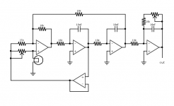
With the lamp-stabilized osc, a separate 071 could be used as the lamp-driving buffer (!) also leaving the 4th opamp free to do some post-filtering and signal cleanup. Separating the buffer would also mean that the "signal" opamps be thermally decoupled (and electrically as well) from the lamp buffer amp.
The 27k "tweak" resistor could be routed directly from the opamp B in this case.
The diode-stabilized circuit as on ESP site would have a better behavior if tweaked around the diffamp. Especially the diode clamp would be imho better if the I/V knee would soften; there are simple ways to do that, fe. with a series resistor. A small SMD bridge would be beneficial as well. Best would be B-E transistor junctions; but using matched duals would defeat the purpose of "cheap & cheerful".
I mean the diode svf osc leaves one last opamp for additional filtering so maybe that could add some to the final performance.
With the lamp-stabilized osc, a separate 071 could be used as the lamp-driving buffer (!) also leaving the 4th opamp free to do some post-filtering and signal cleanup. Separating the buffer would also mean that the "signal" opamps be thermally decoupled (and electrically as well) from the lamp buffer amp.
The 27k "tweak" resistor could be routed directly from the opamp B in this case.
The thing to look at is where you start. A degenerated diode limiter would be about - 12dB F3, the Elektor I measured at -66db F3 ( 3rd ) at the lamp and no obvious other harmonics ( only thing I could measure, the rest is too low ). If we take 12 from 66 we get 54 dB difference in the starting point. If we remove 54 from 108 of Elektor we get - 54 dB which is about where the Analogue Cookbook SVF gets before the 91K 10 K phase summing. As you saw my version got -70db or better. The simulation posted was very interesting.
Look how good a lamp can be.
Injection-Lock a Wien-Bridge Oscillator | Analog Devices
Look how good a lamp can be.
Injection-Lock a Wien-Bridge Oscillator | Analog Devices
Analog Circuits Cookbook - Ian Hickman - Google Books
Hopefully this link opens. I remember reading this book in Oxford library when it came out. The next pages good also. Op amp with it's head in the clouds if I remember.
Hopefully this link opens. I remember reading this book in Oxford library when it came out. The next pages good also. Op amp with it's head in the clouds if I remember.
... but they used a LT1468 turbo-opamp with it.
In above post I suggested to try a physically separate opamp to drive the "lamp". This would separate the "signal" tl074 from the buffer opamp, and free the 4th opamp to perform some additional post-filtering. Like the picture below.
Wrt the diode-stabilized circuit, a diode-quad (fe a bridge) would smooth the flat-topping by itself, but could be piece-wise further smoothed with series/parallel resistors. That would no doubt bring the 3rd down by a coupla dBs. But how much?
Attachments
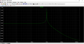
The guy from Elektor is saying much the same. He uses a simple passive filter at the end to get > -108dB. By maths it could be -117 dB. I suspect the Elektor and outher SVF cancell the second harmonic as the Elektor SVF seemes to have lower distortion than the TL074 itself!
I have 10 kHz on my version for these reasons. It's enough to test the JLH and the first troubling harmonic if the ears is 30 kHz. Also the TL074 graph is good until 10 kHz. 1kHz is useful. I have a hunch the Elektor can do 10 kHz -100 dB.
I am back in my shed Tuesday. At the moment I am being paid to think about electricity in Norway.
YouTube
I wonder if this is what I should buy? Twice as much as I should pay and a bit limited. He talks of a Freeware device in an other presentation. He seems not to give all the imformation to track them down. I wonder if he collects test gear. I doubt he ever got his money back as work tools.
I wonder if this is what I should buy? Twice as much as I should pay and a bit limited. He talks of a Freeware device in an other presentation. He seems not to give all the imformation to track them down. I wonder if he collects test gear. I doubt he ever got his money back as work tools.
This is a good read. JLH perfect class A and this perfect class B. I have a hunch this beats the Quad 405. Same era as JLH.
http://www.keith-snook.info/wireles... to class-B Amplifier Design by P Blomley.pdf
http://www.keith-snook.info/wireles... to class-B Amplifier Design by P Blomley.pdf
I'm mostly using either an old test signal CD (John E. Janowitz's Stryke's BassZone Test CD Vol.1 ) or an app on my phone (Audio Function Generator, free version) for general purpose testing
But I do need an LFO for a tremolo circuit however a diode limited Wien bridge will do nicely. There's a lot of leads on the wikipedia page for these for better ways to do it (e.g. William's works)
But I do need an LFO for a tremolo circuit however a diode limited Wien bridge will do nicely. There's a lot of leads on the wikipedia page for these for better ways to do it (e.g. William's works)
Possible Purchase ?
Hi All,
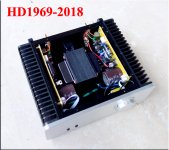
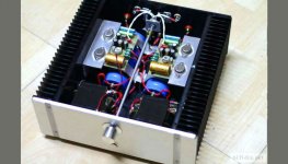
I am thinking of purchasing a Taobao JLH 1969 Class A amplifier, the "HD1969-2018 version", 718.00 yuan (about $113usd plus shipping). Any feedback on the photos ? I wish I had the ability to build the JLH 1969 Class A amp myself, but I already have too many unfinished projects.
Also found this website on the JLH 1996 Amp on a Russian website, any thoughts ?
Thank you !
P.S. I would would welcome any suggestions for a builder to help me complete some of my DIY projects.
Hi All,
I am thinking of purchasing a Taobao JLH 1969 Class A amplifier, the "HD1969-2018 version", 718.00 yuan (about $113usd plus shipping). Any feedback on the photos ? I wish I had the ability to build the JLH 1969 Class A amp myself, but I already have too many unfinished projects.
Also found this website on the JLH 1996 Amp on a Russian website, any thoughts ?
Thank you !
P.S. I would would welcome any suggestions for a builder to help me complete some of my DIY projects.
Attachments
Last edited:
- Home
- Amplifiers
- Solid State
- JLH 10 Watt class A amplifier